Inovonics FA422 User Manual
Page 9
FA422 Installation Manual
Page 9 of 11
02793.FM
Installation
1.
Remove power from the control panel.
2.
Remove the temporary cables between the panel and the keypad, and panel and the Expander.
3.
Determine an appropriate indoor location to mount the Expander. (The housing is designed for indoor use only. ) Do not
enclose the Expander in a metal box. To assure peak performance, avoid mounting the Expander on a metal surface or near
large metal objects
4.
Run the cable wiring from the panel to the Expander. Avoid running the wiring next to electrical, telephone, or other data
wiring. Refer to the panel installation instructions to determine maximum cable length and other wiring details
5.
Route the cable wiring into either the side or back of the Expander. If the wiring is routed through the back of the
Expander, use a small side cutter or utility knife to remove the wiring knockout. If the wiring is routed through the side,
lift out the wiring shutter. (See Figure7. )
6.
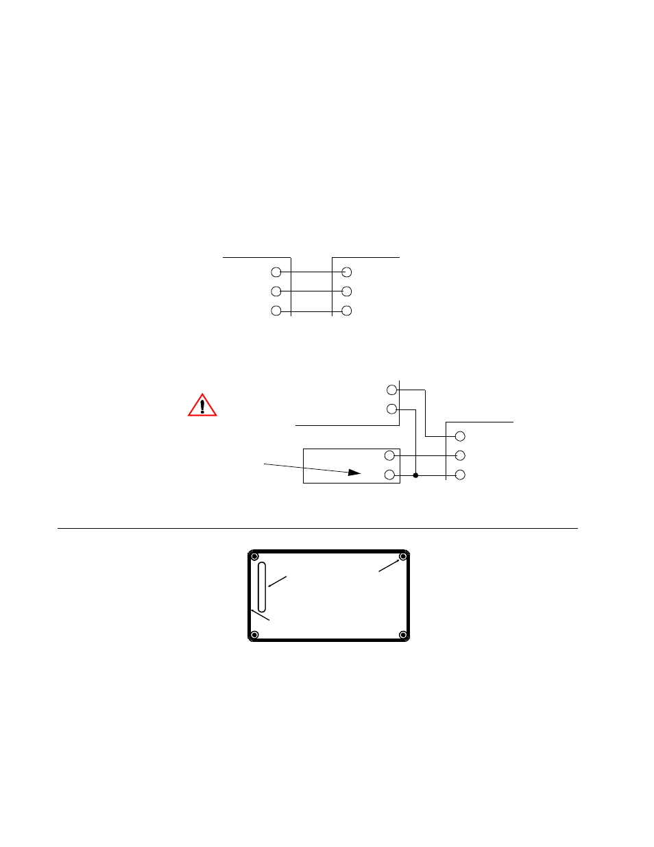
If DC power is supplied by the panel, connect the cable wires from the panel to the Expander as follows:
7.
There may be some installations where DC power to the Expander must be supplied by an external DC power supply.
Refer to the panel installation instructions for further details. If DC power is supplied from an external DC power supply,
connect the cable wires from the panel to the Expander as follows:
8.
Mount the expander to a wall or surface using the supplied hardware. (See F igure7.)
FIGURE 7
FA422 Housing Base
DATA
AUX +
AUX –
Data
Aux +
Aux –
Radionics Panel
FA422 Expander
Radionics Panel
FA422 Expander
DATA
AUX +
AUX –
Data
+
–
Power Supply
Aux –
CAUTION:
Make sure power supply "—"
(negative) terminal is isolated
from earth ground.
Wiring knockout
Wiring shutter
Mounting holes
(4 places)