4 return to factory configuration, 3 connect input/output cabling, 4 mount the receiver – Inovonics EN4204R User Manual
Page 3
7.24.14 05617D © Inovonics, 2014 - www.inovonics.com
3
Output (relay)
• 1, 2, 3, 4. When you are choosing the output, the “Output” LED will
light, along with the LED that indicates the selected output number.
Figure 5 Select the output number
Output type
• Follow, Moment, Toggle, Latch. When you are choosing the output,
the “Out Type” LED will light, along with the LED that indicates the
selected output type.
Figure 6 Select the output type
To program any of the four transmitter points:
1. Use the advance button to select any of the four transmitter points.
• Press the advance button one time to select the first point; the first
LED will light.
• Press the advance button two times to select the second point; the
second LED will light.
• Press the advance button three times to select the third point; the third
LED will light.
• Press the advance button four times to select the fourth point; the
fourth LED will light.
2. Press the program button to begin programming the point.
Note: The program button should be pressed within a few seconds of
selecting the point number. If not, the point number will not be lit, and you
will need to select it again.
• If no transmitter has been registered to the chosen point, the receiver
advances to the supervision window option.
• If a transmitter has already been registered to the chosen point, the
delete LED lights. Press advance to delete the point and return to
normal operation; press program to advance to the supervision
window option.
3. Use the advance button to choose a supervision window of None, 2h,
4h and 96h (Fig. 4).
• Press the advance button one time to select none.
• Press the advance button two times to select two hours.
• Press the advance button three times to select four hours.
• Press the advance button four times to select 96 hours.
When you have selected the supervision window, press program to
complete and advance to the output option.
4. Use the advance button to select the output number (Fig. 5).
• Press the advance button one time to select the first output.
• Press the advance button two times to select the second output.
• Press the advance button three times to select the third output.
• Press the advance button four times to select the fourth output.
When you have selected the output number, press program to complete
and advance to output type option
5. Use the advance button to select the output type (Fig. 6),
• Press the advance button one time to select follower. In follower the
output reflects the transmitter’s alarm status.
• Press the advance button two times to select momentary. In
momentary the output turns on for seven seconds, then turns off,
regardless of the device status.
• Press the advance button three times to select toggle. In toggle the
output changes state each time the device sends a new activation. A
minimum of four seconds must elapse before the output can send a
new activation.
• Press the advance button four times to select latching. In latching the
output turns on when activated and remains on until the receiver is
reset.
When you have selected the output type, press program to complete
and advance to the switch type option.
6. All the option LEDs will light and the point you’ve just programmed will
flash. If you wish to register a transmitter to the point you’ve just
programmed, press the transmitter’s reset button; otherwise, press
program to save programming changes without registering a
transmitter.
Note: The registration is not complete until all LEDs turn off and the point
number lights.
All of the alert LEDs will turn off when the receiver has received the
transmitter’s registration message, and the point number LED will light for
two seconds. This indicates the receiver has received the transmitter’s
registration message. If this does not occur, press reset on the transmitter
again.
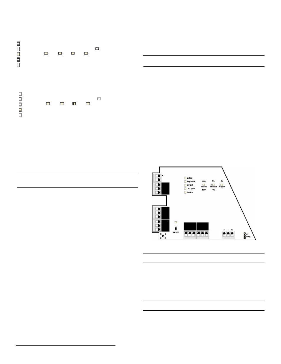
3.3 Connect Input/Output Cabling
The tamper output, jam output and reset input are open collectors, not dry
contacts.
1. Connect cabling to the tamper output.
• The optional tamper output is a normally open (N/O) output that
reports receiver case tamper to an external device.
2. Connect cabling to the jam output.
• The optional jam output is a normally closed (N/C) output that opens
when noise thresholds on all transmission channels remain above a
predetermined value for any 30 seconds in any 60 second window.
The jam output is is set to the follow output type.
3. Connect cabling to the reset input.
• The optional reset input circuit permits installation of a remote
momentary normally open (N/O) switch to clear faults, unlatch outputs
and reset the receiver to a normal state.
4. Connect cabling to the output terminals.
5. Close receiver housing.
Figure 7 EN4204R terminals
3.4 Mount the Receiver
Caution: Mount the receiver in a location removed from metal. Metal
objects (duct work, wire mesh screens, boxes) will reduce RF range.
1. Use the provided anchors and screws to mount the receiver in a
location accessible for future maintenance.
2. Perform a walk test, activating each transmitter assigned to the receiver
and ensuring an appopriate response.
4 Return to Factory Configuration
The EN4204R four zone add-on receiver with relay outputs can be returned
to factory defaults using the following .
Caution: The factory config will erase all programmed point, output, and
language information.
To restore the factory configuration defaults to the receiver:
1. Hold down the reset and advance buttons.
2. With the buttons held down, cycle power.
Delete
Out Type
Output
Sup Wind
Switch
F
Toggle
4h
Latch
96h
Follow
None
N/O
Moment
2h
N/C
1
2
3
4
Delete
Out Type
Output
Sup Wind
Switch
F
Toggle
4h
Latch
96h
Follow
None
N/O
Moment
2h
N/C
1
2
3
4
Vs
Jam output
Ground
Ta
m
p
e
r
Reset i
n
p
u
t
Caution: Incorrect
connections may cause
damage to the unit
NC
COM
NO
NC
COM
NO
NC
COM
NO
NC
COM
NO
NC
COM
NO