Hardy Panel Mount Wall System User Manual
Page 2
Wiring:
1. Once the PMWS is installed, re-open for easy access to sensor,
communications and power connections.
Caution:
Make sure the power is shut off before connecting any
wires into the Panel Mount Wall System.
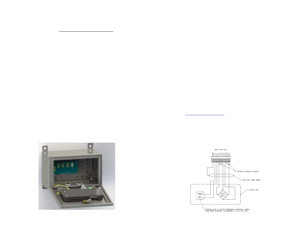
2. Wire load sensors to their respective locations on the summing
card. If only a single sensor is being used, remove and wire to the
quick-disconnect located on the bottom of the instrument.
a. If conduit is used, do not run load cell cable parallel to, or in the same
conduit with, power wiring, relay cable or other high energy cables.
b. Factory installed jumpers are to remain in place only for four wire, non
C2 load cell connections. Excitation and sense wires are to be
connected together to the summing card.
c. C2 cable is required for weightless calibration and INTEGRATED
TECHNICIAN® (IT) (Hardy Process Solutions P/N 6020-0001).
d. See Users Guide for additional information on load cell connections. A
complete User’s Guide can be found under Documents and Programs
online:
www.hardysolutions.com
Navigate to the Product menu>
Weighing Instruments > Weight Processors > HI 6500 (or HI 6300).
The User Guide is on the Docs & Programs tab.
e. Terminal block wire size range: 22 AWG minimum / 16 AWG
maximum. Wire temperature rating to be 90° C. Wire tightening
torque is to be 2 lbs-in minimum / 4 lbs-in maximum.
f. For clarity, only one load sensor connection is shown.
Enclosure Installation:
1. Locate and remove the Enclosure Bracket Hardware Bag inside the
enclosure along with enclosure manufacturer instructions.
2. Determine an enclosure mounting scheme that best fits your
installation requirements. Brackets can be placed vertically or
horizontally in relation to the enclosure (vertical shown below).
3. Install enclosure brackets.
4. Install glands for wiring. (Do not remove integrated gland plug from
glands that will not be used for wiring).
Note:
If using an AC/DC power converter, install the converter
to the right of the summing card and wire the DC out to
the instrument before mounting. Pre-drilled holes for
DIN rail installation can be found on the enclosure back
mounting plate.
Caution:
You must use a power-limited 12-24 VDC power supply
(Class 2) on the DC input wiring. DC power should be
supplied by a clean primary line, directly from the DC
power source.
5. Place enclosure at its installation location, mark for wall or structure
mounting and drill holes.
6. Install enclosure.