Hardy HI 4050 Single-Scale Weight Controller User Manual
Quick installation guide
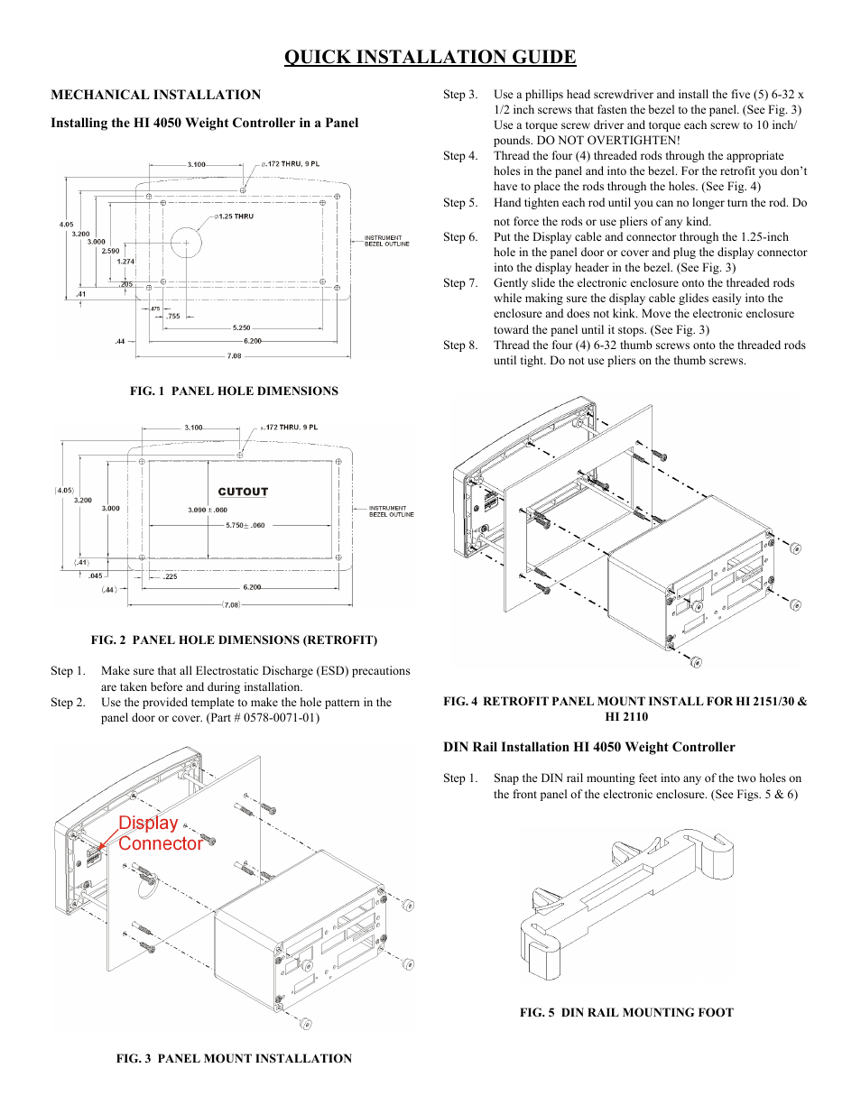
Table of contents
Document Outline
- Quick Installation guide
- Mechanical Installation
- Installing the HI 4050 Weight Controller in a Panel
- FIG. 1 panel HOLE DIMENSIONS
- FIG. 2 Panel hole dimensions (retrofit)
- FIG. 3 panel mount installation
- Step 3. Use a phillips head screwdriver and install the five (5) 6-32 x 1/2 inch screws that fasten the bezel to the panel. (See Fig. 3) Use a torque screw driver and torque each screw to 10 inch/ pounds. DO NOT OVERTIGHTEN!
- Step 4. Thread the four (4) threaded rods through the appropriate holes in the panel and into the bezel. For the retrofit you don’t have to place the rods through the holes. (See Fig. 4)
- Step 5. Hand tighten each rod until you can no longer turn the rod. Do not force the rods or use pliers of any kind.
- Step 6. Put the Display cable and connector through the 1.25-inch hole in the panel door or cover and plug the display connector into the display header in the bezel. (See Fig. 3)
- Step 7. Gently slide the electronic enclosure onto the threaded rods while making sure the display cable glides easily into the enclosure and does not kink. Move the electronic enclosure toward the panel until it stops. (See Fig. 3)
- Step 8. Thread the four (4) 6-32 thumb screws onto the threaded rods until tight. Do not use pliers on the thumb screws.
- FIG. 4 rETROFIT pANEL MOUNT INSTALL FOR hi 2151/30 & hi 2110
- DIN Rail Installation HI 4050 Weight Controller
- Step 1. Snap the DIN rail mounting feet into any of the two holes on the front panel of the electronic enclosure. (See Figs. 5 & 6)
- FIG. 5 din rail mounting foot
- FIG. 6 vertical and horizontal orientation
- Step 2. When installing firmly push the mounting feet until you hear a snapping sound. The snap means they are mounted correctly.
- Step 3. After installation give each mounting foot a little tug to make sure they are seated correctly.
- Step 4. To mount the enclosure onto a DIN rail. Place the mounting feet on the DIN Rail and firmly press down until the mounting feet snap onto the rail.
- Step 5. To remove the mounting feet use a finger on the clip and gently pull up on the tab.
- Load Point Installation
- C2® Load Point Connection
- Step 1. Remove the factory installed jumpers from the terminal block if you are connecting an 8 wire cable from the junction box. (See Fig. 8)
- Step 2. Connect the cable (Recommended load cell cable: Hardy Instruments Part # 6020-0001) wires to the Weigh Scale Inputterminal block according to the cable color chart.
- Step 3. Plug the terminal block into the Weigh Scale Input connector on the rear panel.
- Step 4. For more information concerning C2 Load Point connection, consult Chapter 3, Installation, of the HI 4050 User Guide.
- Non-C2 Load Point Connection
- Step 1. Remove the factory installed jumpers from the terminal block if you have a 6-wire load cell cable that includes sense wires from the load cell or junction box.
- Step 2. Connect the cable (Recommended load cell cable: Hardy Instruments Part # 6020-0001) wires to the Weigh Scale Input terminal block according to the manufacturer’s specification.
- Step 3. Plug the terminal block into the Weigh Scale Input connector on the rear panel.
- Input Power Wiring
- WARNING: Do not plug the power connector into the header with live power. To do so will result in property damage and/or personal injury.
- WARNING: if a lithium battery is replaced with an incorrect type it may cause an explosion which will cause property damage or personal injury.
- AC Input Power Wiring (-AC)
- WARNING: do not operate with incorrect line voltage. to do so will result in property damage and/or personal injury. Make sure that the power source does not exceed 240 VAC.
- WARNING: If an automatic disconnect device is used on the AC input wires, the disconnect must act on both the line and neutral wires in a double pole, double throw arrangement i.e. DPDT Relay. Using other automatic disconnect arrangements may cause p...
- Step 1. The HI 4050 is configured with a universal power supply rated from 110 to 240 VAC.
- Step 2. Make sure the VAC power is shut off before installing the wires to the connector.
- Step 3. Install a 3-wire, minimum 14 AWG power line to the 3-pin terminal block connector. Make sure that the shield is connected to the local Earth Ground connection.
- DC Power Input (-DC)
- WARNING: do not operate with incorrect line voltage. to do so will result in property damage and/or personal injury. Make sure that the power source does not exceed 24 VDC.
- Step 1. Make sure the VDC power is shut off before installing the wires to the connector.
- Step 2. Connect the 24 VDC Voltage wire, Ground wire and Shield wire to the connector that plugs into the DC voltage header at the rear panel. Make sure that the shield is connected to the local Earth Ground connection.
- Step 3. Plug the connector into the header at the rear panel. (See Fig. 7)
- Starting the HI 4050