Load cell wiring diagrams, Hi 1756 1df valve wiring diagram – Hardy HI 1756-nDF User Manual
Page 13
9
●
●
●
●
●
Chapter 3
Check to be sure that the connector is completely
plugged in before operating the module.
NOTE
Most module-related problems are due to loose
connections. Be sure to check the I/O connection first
in the event you have a problem receiving
information from the load cells or if the relays do not
operate correctly.
Single Channel
Pin 1 Exc+
Pin 2 Sense+
Pin 3 Sig+
Pin 4 Sig-
Pin 5 Sense-
Pin 6 Exc-
Pin 7 C2+
Pin 8 C2-
Pin 9 Shield
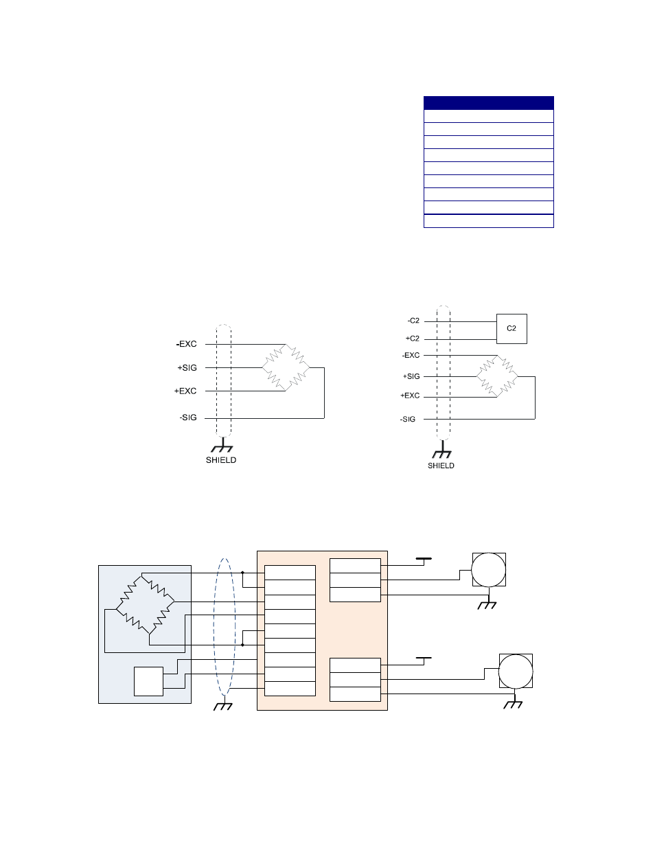
Load Cell Wiring Diagrams
The diagrams below show how Hardy Load Sensor with C2 wiring differs from standard
Load Cell wiring. C2 wiring is required when using a Integrated Technician summing
junction box. The C2 wires are used fro communicating IT and C2 commands.
Industry standard load cells wiring
Hardy load sensor/c2 wiring
HI 1756 1DF Valve wiring diagram
+Exc
-Exc
+Sen
+Sig
-Sig
-Sen
+C2
-C2
Shield
RA1 IP
RA1 OP
RA1 COM
RB1 IP
RB1 OP
RB1 COM
1756-1DF
C2
Shield
Load Cell
(0-24Vdc, 3.5A)
Valve
1
(0-24Vdc, 3.5A)
Valve
2
Control Voltage 2
Control Voltage 1
COM2
COM1