3 | areas of application – GEA Bock HGZ7 User Manual
Page 11
D
GB
F
E
11
09726-11.2014-DGbF
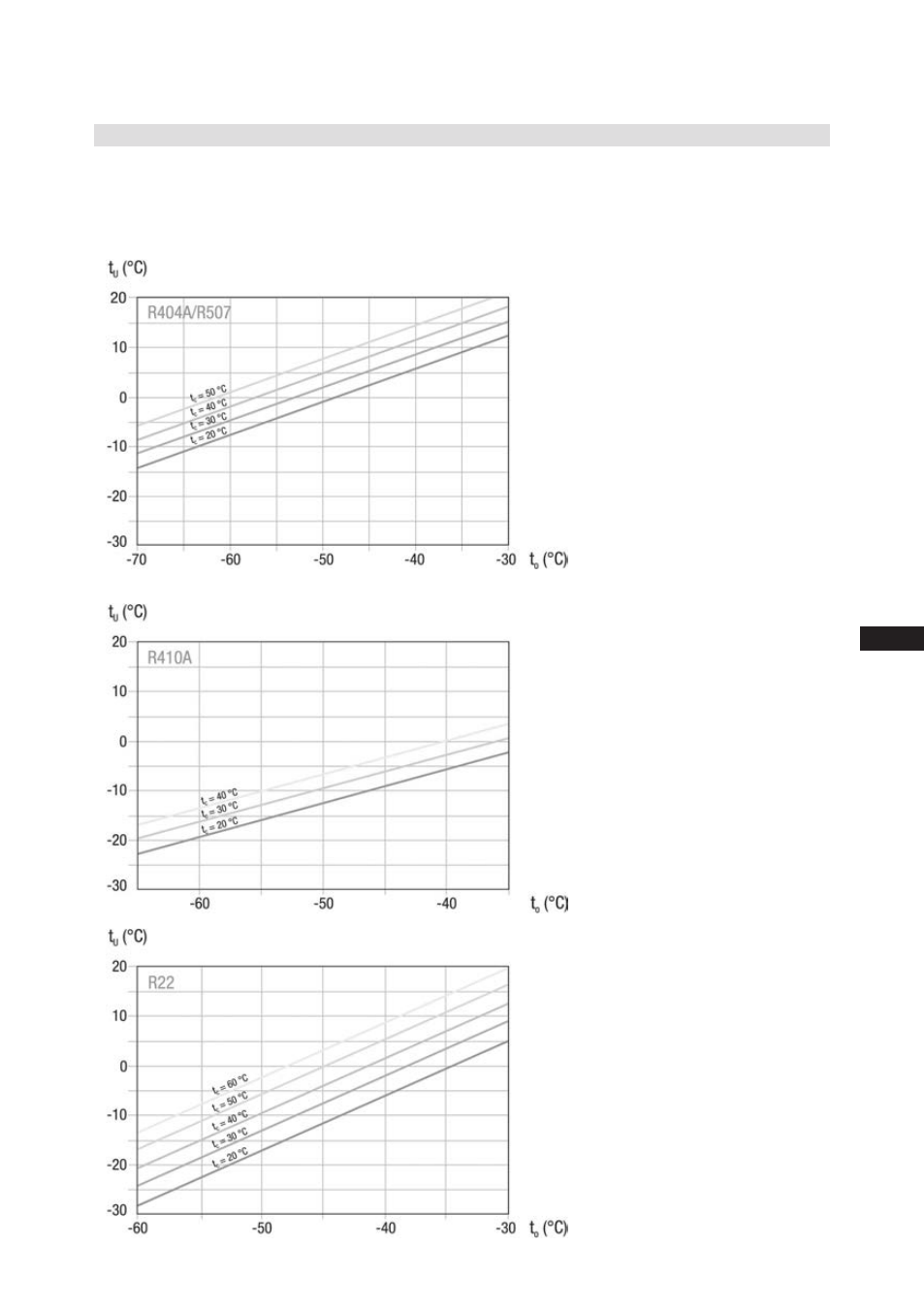
3 | Areas of application
The design of the expansion valve on the compressor can be defined with the help of the diagram by
approximately calculating the subcooling temperature arising in the relevant operating
conditions (t
0
/t
c
).
Diagrams for determining the subcooling temperature at the output of the liquid subcooler.
3.4 Subcooling temperature
t
U
= Subcooling temperature at the
subcooler outlet (FUA)
t
O
= Evaporating temperature
Fig. 10
Fig. 11
Fig. 12
See also other documents in the category GEA Bock Air equipment:
- HG5 (32 pages)
- HG7 (34 pages)
- HG4 (32 pages)
- HG6 (32 pages)
- HG8 (38 pages)
- HG34e (30 pages)
- HG22Р (26 pages)
- HG12Р (26 pages)
- BCM2000 (18 pages)
- HG22e (26 pages)
- HG34P (26 pages)
- HG88e (38 pages)
- HG44e (34 pages)
- HА4 (32 pages)
- HА34P (26 pages)
- HA12P (26 pages)
- HA5 (32 pages)
- HA6 (32 pages)
- HG22Р CO2 (28 pages)
- HG34P CO2 (28 pages)
- HG4 CO2 (30 pages)
- HG12Р CO2 (28 pages)
- HG12e CO2 (28 pages)
- HGX2 CO2 T (28 pages)
- HGX34 CO2 T (40 pages)
- HGX46 CO2 T (40 pages)
- HAX2 CO2 T (28 pages)
- HG5 R134a (32 pages)
- HG6 R134a (32 pages)
- HG7 R134a (32 pages)
- HG4 R134a (32 pages)
- F (44 pages)
- F18 (28 pages)
- FK40 (26 pages)
- FK30 (26 pages)
- FK50 (26 pages)
- FK20 (26 pages)
- HG22P A (28 pages)
- HG34e A (28 pages)
- HG22e A (28 pages)
- HGX34P 2 pole (32 pages)