5 | electrical connection – GEA Bock HG7 User Manual
Page 20
20
D
GB
F
E
I
Ru
09706-01.2015-DGbFEIRu
5| Electrical connection
Terminal box
Fig. 21
Temperature monitoring connections:
Motor winding:
Terminals 1 - 2
Thermal protection thermostat:
Terminals 3 - 4
Restart prevention:
Terminals 5 - 6
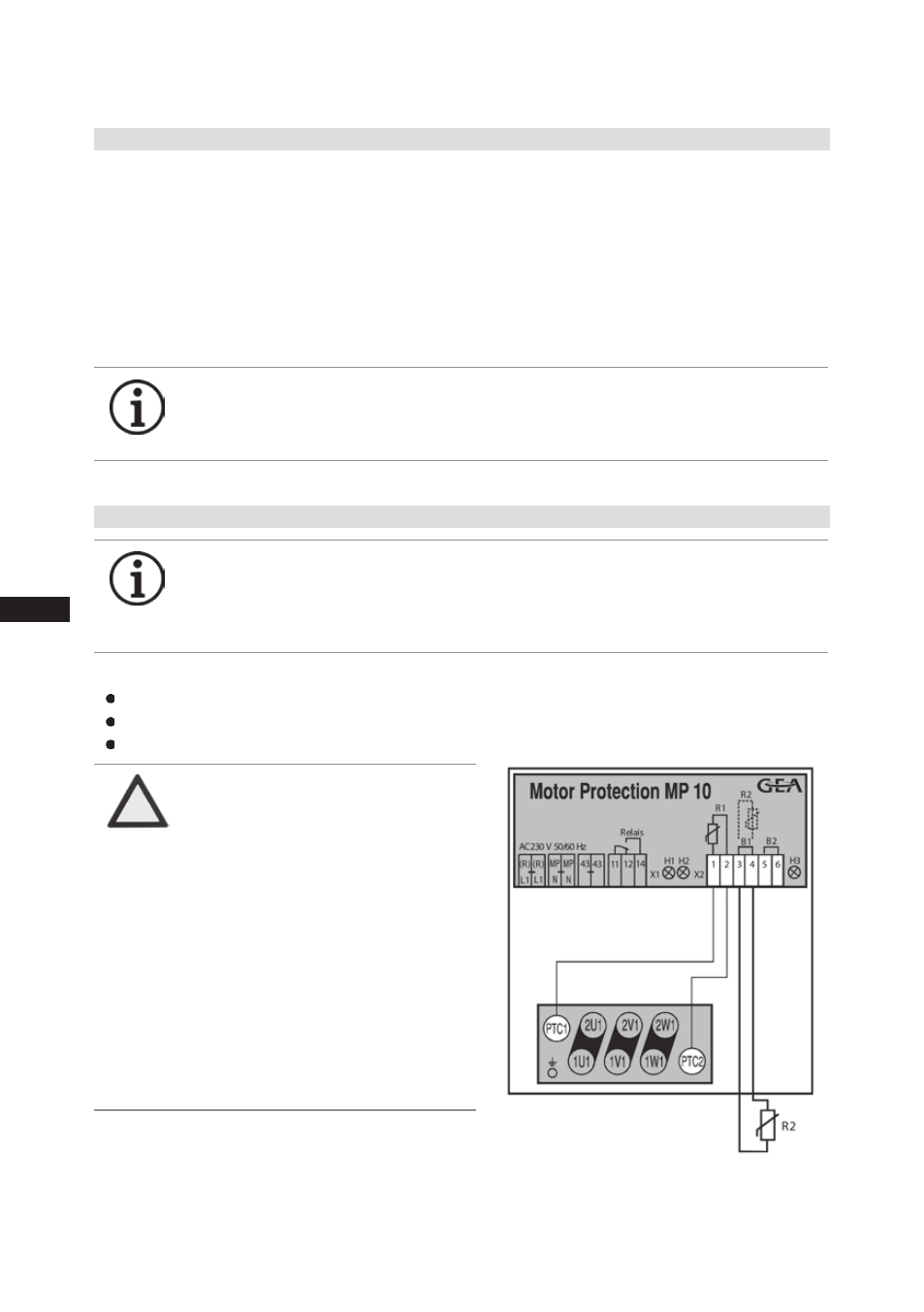
5.6 Electronic trigger unit MP 10
The compressor motor is fitted with cold conductor temperature sensors (PTC) connected to the
electronic trigger unit MP 10 in the terminal box. Readiness to operate is signalled by the H3 LED
(green) after the power supply is applied. In the case of excess temperature in the motor winding, the
unit switches off the compressor and the H1 LED lights red.
The hot gas side of the compressor can also be protected against overtemperature using a thermal
protection thermostat (accessory). The H2 LED (red) is provided for the protection function.
The unit trips when an overload or inadmissible operating conditions occur. Find and remedy
the cause.
5.7 Connection of the trigger unit MP 10
ATTENTION
Terminals 1 - 6 on the trigger
unit MP 10 and terminals PTC
1 and PTC 2 on the compressor
terminal board must not come
into contact with mains voltage.
This would destroy the trigger
unit and PTC sensors.
The supply voltage at L1-N
(+/- for DC 24 V version) must
be identical to the voltage at
terminals 11, 12, 14 and 43.
INFO
Connect the trigger unit MP 10 in accordance with the circuit dia-
gram. Wire the trigger unit as the first member in the control power
circuit and protect it with a fuse that is rated no larger than the
smallest maximum permissible current of the installed component.
INFO
The unit has a restart prevention device. After you have rectified the
fault, interrupt the mains voltage. This unlocks the restart prevention
device and the LEDs H1 and H2 go out.