5 | electrical connection, Yyy y/yy – GEA Bock HG7 User Manual
Page 16
16
D
GB
F
E
I
Ru
09706-01.2015-DGbFEIRu
400 V
Direktstart YY
Teilwicklungsstart Y/YY
1V1
1W1
1U1
2W1
2V1
2U1
L3
L2
L1
L3
L2
L1
L3
L2
L1
1V1
1W1
1U1
2W1
2V1
2U1
Direct start
Part winding start
The motor is wired for direct start (YYY resp. YY) at the factory. For part winding start
Δ/YYY resp.
Y/YY the bridges must be removed and the motor feed line connected according to the circuit diagram:
5.3 Standard motor, design for direct or part winding start
5| Electrical connection
INFO
A mechanical unloaded start with bypass solenoid valve is
not required.
ATTENTION Failure to do this results in opposed rotary fields and results in
damage to the motor. After the motor starts up via partial winding
1, partial winding 2 must be switched on after a maximum delay
of one second . Failure to comply can adversely affect the service
life of the motor.
INFO
When testing coils with resistance tester, please note that partial
winding 1 and partial winding 2 are wired internally in HG7.
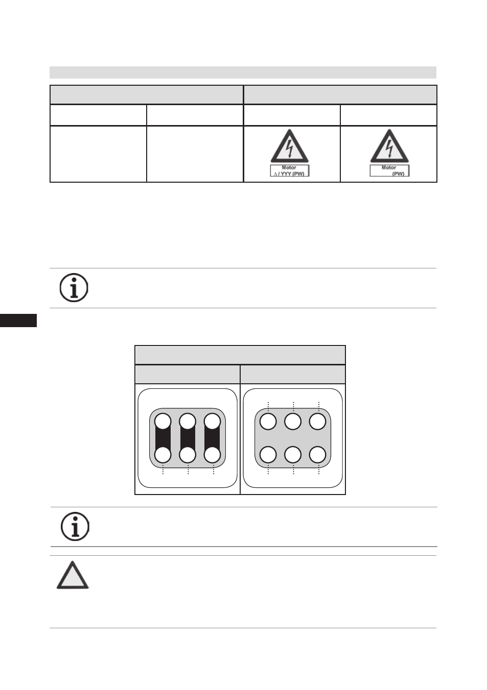
Designation on the name plate
Sticker on the terminal box
until A039
from A040
until A039
from A040
∆/YYY
Y/YY
Y/YY
Compressors with this marking are suitable for direct or partial winding start. The motor winding is
subdivided into two parts:
Until type code A039: Part winding 1 = 60% and part winding 2 = 40%. This winding division
reduces the start-up current needed for a part winding start to approx. 65% of that for a direct start.
From type code A040: Part winding 1 = 50% and part winding 2 = 50%. This winding division
reduces the start-up current needed for a part winding start to approx. 50% of that for a direct start.