Erica Synths DIY Polivoks VCO kit User Manual
Page 9
➑
Solder potentiometers
➒
Insert ICs. Mind the orientation.
10
Wash the PCB to eliminate the flux
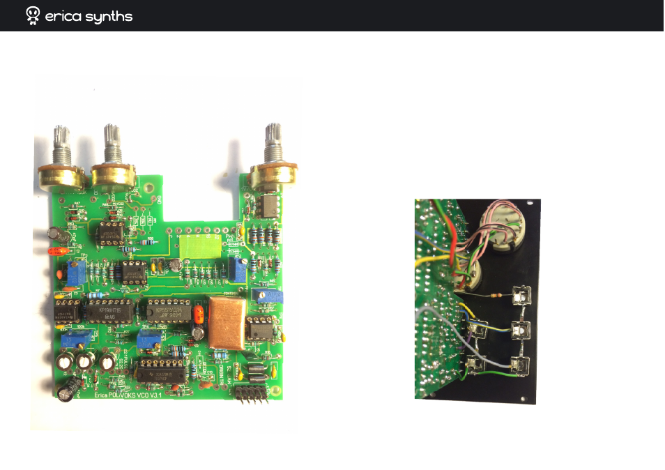
11
Install jacks and switches (if you are using rotary switches provided
with the full kit, use special washers to configure them to 5 and 6 positions
correspondingly) in the front panel. Connect all GND lugs of the jacks to
the GND of the PCB. Note that R64 is off board and goes from PWM jack to
the rotary switch S2.2. Insert the PCB in relevant holes of the panel and
wire it to the panel controls (see the wiring diagram below). VCO2 has
Output2 option – you can wire it parallel to the Main Output, take some
one of the waveforms, or use it for Original Triangle Output (see the
silkscreen on the PCB – ORIGIN. TRI), like I did. 1V/oct and PWM jack
switches should be normaled to the GND.
CONGRATULATIONS! YOU HAVE COMPETED HARDWARE PART!