Erica Synths DIY Polivoks VCO kit User Manual
Page 6
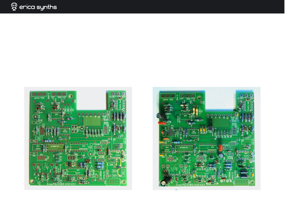
➌
Populate PCB with resistors and diodes.
NB! PCB V3.1 HAS MISTAKEN
SILKSCREEN; YOU HAVE TO SWAP TWO RESISTORS: R68 HAS TO BE 2K7,
AND R3 HAS TO BE 1K. IF YOU DO NOT DO SO, YOU WILL NOT BE ABLE TO
TUNE THE VCO.
The PCB has silkscreen both of resistor values and desig-
nations. I strongly recommend using all 1% resistors, especially, if you are
building both VCOs, but if you do not do so, there are several resistors that
MUST be 1%. Those are mentioned in the schematics and noted with * on
the PCB silkscreen. I recommend to hand-match 10k resistors in octave
divider (R34-R37). They do not need to be exactly 100k, but all four resistors
have to be as close as possible, for example, my resistors measured 99,7k.
You can modify output waveform amplitudes and offsets. If you want to do
so, see the schematics for R57 and R32 options.
➍
Solder all capacitors and ferrite beads. Put aside cut off legs of the
ferrite beads – you will need them later. NB! The original Polivoks trian-
gle waveform has a sharp spike. Erica Synths Polivoks VCO version can
filter this spike out for a better triangle waveform. To obtain original
sharp waveform, a few components need to be omitted or altered. Omit-
ting C11 C12 C13 passes the spike to the output unaltered.