Erica Synths DIY Polivoks VCO kit User Manual
Page 8
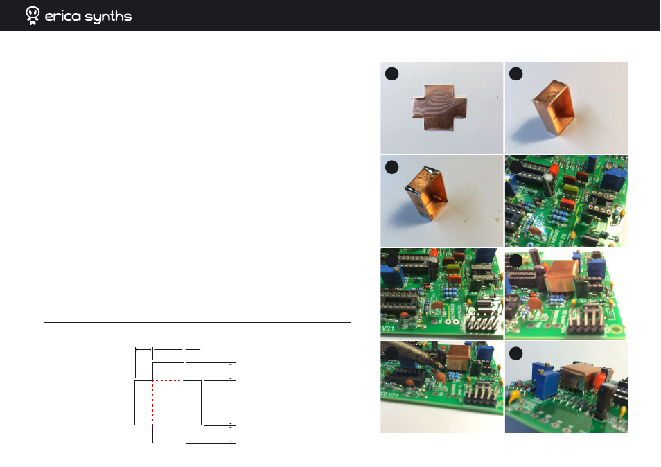
➐
Soviet transistors (KT315 and KT361) are sensitive to light, including infrared. If you do
not intend to tune the VCO in the darkness, it’s time for real DIY challenge! We will use the
copper sheet included in the kit to make the shield for transistors.
a. Use the TEMPLATE below to cut out the shield!
b. Use pliers and, if needed, a small hammer, to bend sides of the shield. You have to end
up with a small box.
c. Set the soldering iron to 350-400oC and solder edges of the box.
d. Solder cut off ferrite bead legs (see the chapter 4 above) in four points around the
transistors on the PCB. One of them is marked GND.
e. Bend them slightly inside, and you have improvised spacers!
f. Put the shield box on top of them; make sure the shield doesn’t touch transistor pins
and R15.
g. Set soldering iron to 350-400oC and solder the shield to the spacers. You may want to
hold a spacer with tweezers to remove extra heat and prevent accidental disordering of
the spacer from the PCB. Three solder joints are ok; it’s hard to access one next to C5.
h. Check, if you do not have accidental connection of transistor pints to the ground! Use
DMM to measure resistance between GND and each of the transistor pins – none should
be less that several kOhm.
Congratulations! The hardest part is behind! This will help to prevent RFI and undesired
detuning of the VCO oscillator.
8 mm
8 mm
8 mm 14 mm
8 mm
20 mm
b.
c.
a.
e.
f.
g.
h.
d.