A-172, System a - 100, In- / outputs – Doepfer A-172 Minimum/Maximum Selector User Manual
Page 4: User examples, Doepfer, Max / min, Max. out, Min. out
A-172
MAX / MIN
System A - 100
doepfer
4
5. In- / Outputs
!
In 1 ... $ In 4
The input signals are connected to these sockets. At
least 2 signals are necessary to obtain the maximum
resp. minimum function. Unused inputs have to be left
open. Do not connect unused inputs to GND as this is
equal to 0V and different from an open socket !
%
Max. Out
This is the Maximum output of the module.
&
Min. Out
This is the Minumum output of the module.
6. User Examples
The main application of the module is the processing
of control voltages, e.g. random voltages, ADSR,
LFO, S&H, ribbon CV, Theremin CV and similar.
To adjust offset and amplitude for each input inde-
pendently (i.e. to bring the signal into the right
"position" with the desired level) we recommend to
combine the module with the A-129-3 Slew Limiter/
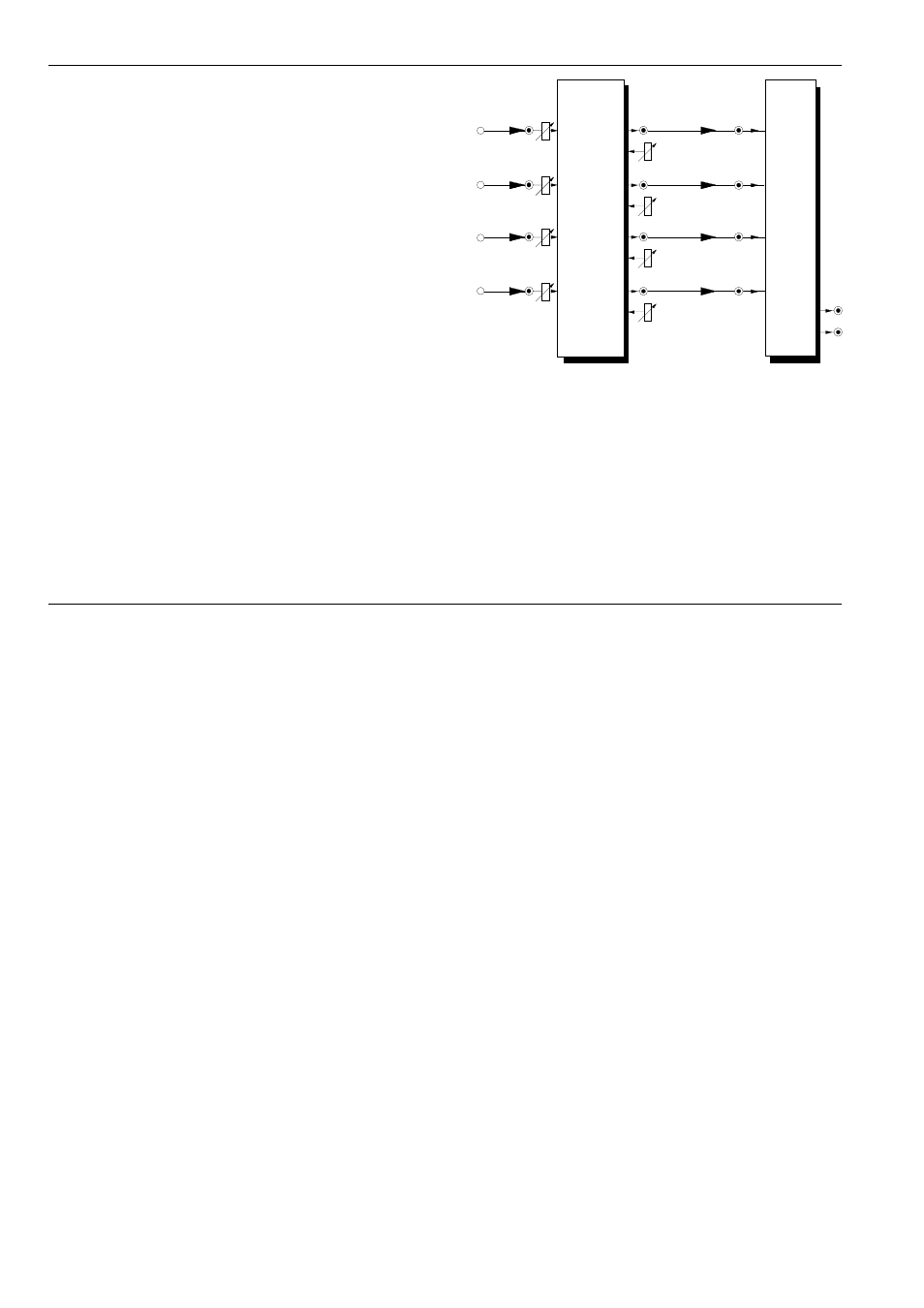
Attenuator/Offset Generator (see fig. 2).
Fig. 2: Max/Min detector with individally adjustable
attenuation and offset for each input signal
The module is useful for audio processing too. Using
the outputs of a VCO as inputs creates new wa-
veforms. Using the outputs of two or more VCOs leads
to new interference sounds that are different from VCO
mixing, ring modulation or hard/soft sync.
Even the combination of control and audio signals
as inputs makes sense and causes a kind of pulse-
width modulation even for saw, triangle or sine by
clipping the upper/lower parts of the waveform.
A-172
MAX / MIN
In 1
Max. Out
Offset
Atten.
CV
In 1
CV
Out 1
A-129 /3
Offset
Atten.
CV
In 2
CV
Out 2
Offset
Atten.
CV
In 3
CV
Out 3
Offset
Atten.
CV
In 4
CV
Out 4
Min. Out
In 2
In 3
In 4
In 1
In 2
In 3
In 4