System a - 100, A-138c, Controls / inputs / outputs – Doepfer A-138 c Polarizing Mixer User Manual
Page 3: Doepfer
doepfer
System A - 100
Polarizing Mixer
A-138c
3
3. Controls / Inputs / Outputs
1
...4 In1 ... In4 (controls)
!
...$ Input 1 ... Input 4 (sockets)
These are the four inputs !...$ of the module with the
corresponding polarizing controls 1...4. In contrast to a
normal attenuator (e.g. the mixer controls A-138 a/b) the
zero position of a polarizing control is in the center of the
rotating angle. This corresponds to position 5 of a nor-
mal attenuator.
Left from the middle position (i.e. turning the knob
counterclockwise) the corresponding input signal is sub-
tracted from the output sum with increasing amount.
Right from the middle position (i.e. turning the knob
clockwise) the corresponding input signal is added to
the output sum with increasing amount.
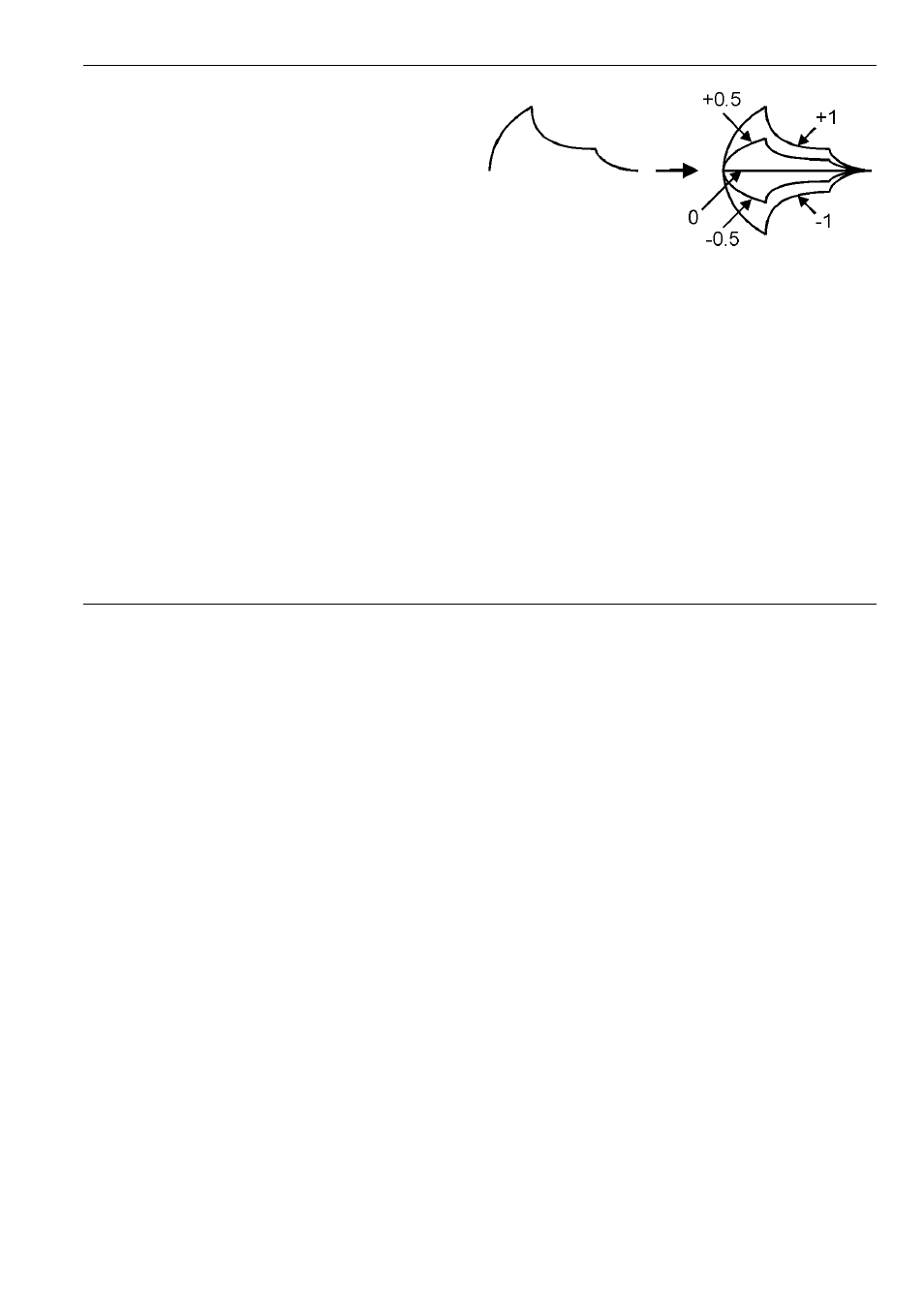
Fig.1 shows the function of a polarizing control by means
of an ADSR envelope as input signal. -1 corresponds to
the fully counterclockwise position of the control, 0 to
middle position and +1 to the fully clockwise position.
5
Out (control) / % Output (socket)
Socket % is the output of the module with the correspon-
ding polarizing output control 5. The output control
works in the same way as the input controls, i.e. the
output sum appearing at socket % can be additionally
attenuated and/or inverted and adjusted to the desired
level.
Fig. 1: Function of the polarizing controls