System a - 100, A-127, Appendix – Doepfer A-127 Triple VC Resonance Filter User Manual
Page 11
doepfer
System A - 100
Triple VC Resonance Filter
A-127
11
7. Appendix
Altering the filter characteristics
The characteristics of each of the indifividual filters in
the A-127 can be altered by changing the position of a
corresponding jumper on its three-pin connector on
the filter circuit-board.
The standard factory setting is for each of the filters to
be set to the bandpass position (labelled "BP").
You can, if you want, alter the response of each
individual filter, so that it is 12 db low-pass.
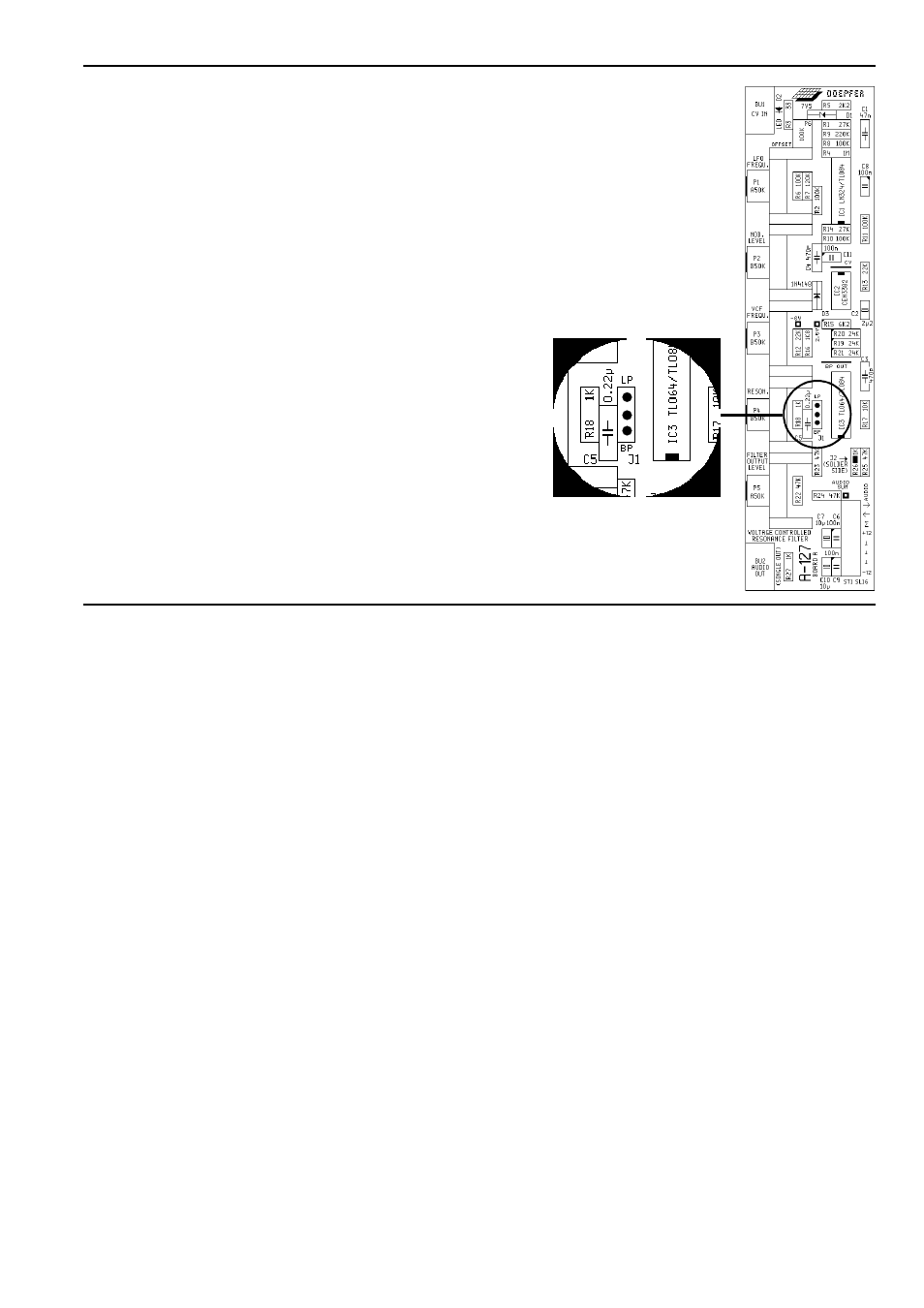
Versions 1 and 2 of the A-127 module:
Change Jumper J1 on the filter circuit board from
position "BP" to position "LP" (low pass) - see Fig. 6.
Version 3 of the A-127 module:
Change the position of Jumper JP5 on the filter circuit.
JP5 is located behind der filter output socket.
Even a toggle switch can be added to switch between
low pass and band pass for each filter.
fig. 6: A-127 filter circuit-board
(versions 1 and 2)
- DIY Synth do-it-yourself analog synthesizer (24 pages)
- MKE Universal Midi Keyboard Electronics Kit (17 pages)
- CTM64 Contact to Midi Interface (main board) (20 pages)
- CTM64 Relay Board (8 pages)
- MTC64 Midi to Gate Interface (main board) (16 pages)
- MTC64 Relay Board (8 pages)
- MTC64 Output Board (transistor driver board) (4 pages)
- MTC64 Power Board (8 pages)
- Pocket Electronic (32 pages)
- Dial Electronic (12 pages)
- Wheel Electronic (16 pages)
- USB64 Universal Midi and USB Controller Electronics Kit (20 pages)
- MBP25 Midi Bass Pedal Electronics Kit (16 pages)
- MTV16 Midi-to-Voltage Interface with 16 Analog Voltage Outputs (8 pages)
- A-100 (8 pages)
- A-100AD5 +5V low cost adapter (46 pages)
- A-100(~ 40 MB) (744 pages)
- A-100CGK CV/Gate keyboard (12 pages)
- A-101-1 Vactrol Steiner Filter (6 pages)
- A-101-2 Vactrol Lowpass Gate (6 pages)
- A-101-3 Vactrol Modular Phase Filter (10 pages)
- A-101-9 Universal Vactrol Module (14 pages)
- A-102 Diode Low Pass (6 pages)
- A-104 four-fold Trautonium Formant Filter (6 pages)
- A-105 24dB SSM Low Pass (8 pages)
- A-106-1 Xtreme Lowpass/Highpass Filter (12 pages)
- A-107 Multitype Morphing Filter (18 pages)
- A-108 6/12/24/48 Formant Filter (10 pages)
- A-109 Voltage Controlled Audio Signal Processor (10 pages)
- A-110 Standard VCO (12 pages)
- A-111-1 High End VCO (14 pages)
- A-111-5 Synthesizer Voice (22 pages)
- A-112 Sampler/Wavetable Oscillator (24 pages)
- A-113 Subharmonic Oscillator (14 pages)
- A-114 Dual Ringmodulator (6 pages)
- A-115 Audio Divider (6 pages)
- A-116 VC Waveform Processor (6 pages)
- A-117 Digital Noise / 808 Source (8 pages)
- A-118 Noise/Random (6 pages)
- A-119 External Input/Envelope Follower (8 pages)
- A-120 24dB Low Pass 1 (8 pages)
- A-121 12dB Multimode VCF (10 pages)
- A-123 24dB High Pass (no longer available) (8 pages)
- A-124 Wasp Filter (8 pages)
- A-125 VC Phaser (8 pages)