A-120, System a - 100, Doepfer – Doepfer A-120 24dB Low Pass 1 User Manual
Page 4
A-120
VCF 1
System A - 100
doepfer
4
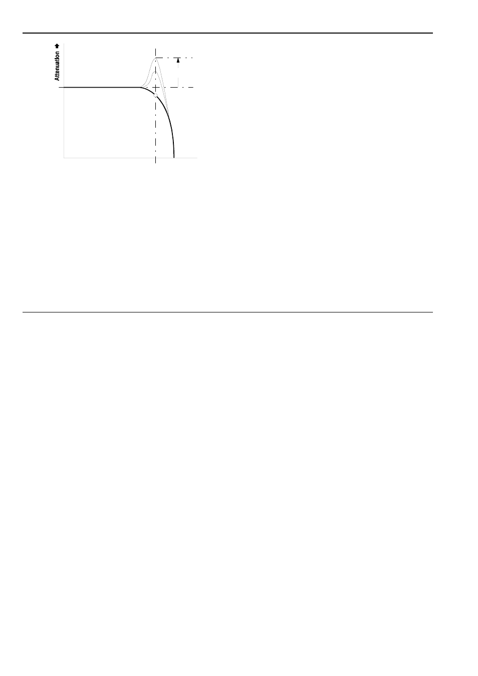
Fig. 2:
How resonance affects the response of a low
pass filter
4. In / Outputs
!
CV 1
Socket CV 1 is the filter’s standard voltage control
input, and works on the 1V / octave rule, like the
VCOs.
If you patch a modulation source (eg LFO, ADSR) to
this input, the cut-off frequency of the filter will be
modulated by its voltage: ie., the sound color changes
according to the voltage put out by the modulator.
If you use the VCF as a sine wave oscillator, connect
the pitch CV into this socket. Do the same if you want
the filter’s cut-off frequency to track exactly with the
pitch of a note.
"
CV 2 • § CV 3
Sockets CV 2 and CV 3 are also voltage control
inputs for the filter. Unlike CV 1, you can control the
level of voltage - the intensity of modulation effect on
the filter - with attenuators 2 and 3.
$
Audio In
This is the filter’s audio input socket. Patch in the
output from any sound source (eg. VCO, noise gene-
rator, mixer).
%
Audio Out
Filter output % sends out the filtered signal.
fc
Resonance
Frequency ➨
➨
➨
➨
0 db
- DIY Synth do-it-yourself analog synthesizer (24 pages)
- MKE Universal Midi Keyboard Electronics Kit (17 pages)
- CTM64 Contact to Midi Interface (main board) (20 pages)
- CTM64 Relay Board (8 pages)
- MTC64 Midi to Gate Interface (main board) (16 pages)
- MTC64 Relay Board (8 pages)
- MTC64 Output Board (transistor driver board) (4 pages)
- MTC64 Power Board (8 pages)
- Pocket Electronic (32 pages)
- Dial Electronic (12 pages)
- Wheel Electronic (16 pages)
- USB64 Universal Midi and USB Controller Electronics Kit (20 pages)
- MBP25 Midi Bass Pedal Electronics Kit (16 pages)
- MTV16 Midi-to-Voltage Interface with 16 Analog Voltage Outputs (8 pages)
- A-100 (8 pages)
- A-100AD5 +5V low cost adapter (46 pages)
- A-100(~ 40 MB) (744 pages)
- A-100CGK CV/Gate keyboard (12 pages)
- A-101-1 Vactrol Steiner Filter (6 pages)
- A-101-2 Vactrol Lowpass Gate (6 pages)
- A-101-3 Vactrol Modular Phase Filter (10 pages)
- A-101-9 Universal Vactrol Module (14 pages)
- A-102 Diode Low Pass (6 pages)
- A-104 four-fold Trautonium Formant Filter (6 pages)
- A-105 24dB SSM Low Pass (8 pages)
- A-106-1 Xtreme Lowpass/Highpass Filter (12 pages)
- A-107 Multitype Morphing Filter (18 pages)
- A-108 6/12/24/48 Formant Filter (10 pages)
- A-109 Voltage Controlled Audio Signal Processor (10 pages)
- A-110 Standard VCO (12 pages)
- A-111-1 High End VCO (14 pages)
- A-111-5 Synthesizer Voice (22 pages)
- A-112 Sampler/Wavetable Oscillator (24 pages)
- A-113 Subharmonic Oscillator (14 pages)
- A-114 Dual Ringmodulator (6 pages)
- A-115 Audio Divider (6 pages)
- A-116 VC Waveform Processor (6 pages)
- A-117 Digital Noise / 808 Source (8 pages)
- A-118 Noise/Random (6 pages)
- A-119 External Input/Envelope Follower (8 pages)
- A-121 12dB Multimode VCF (10 pages)
- A-123 24dB High Pass (no longer available) (8 pages)
- A-124 Wasp Filter (8 pages)
- A-125 VC Phaser (8 pages)