Charging system – Cub Cadet MTD 70 Series User Manual
Page 85
Starters
79
Charging system
Description
Some engines are equipped with a charging system.
The charging system consists of:
• Alternator stator: copper field windings around an
iron core. The stator is attached to the engine
block beneath the flywheel.
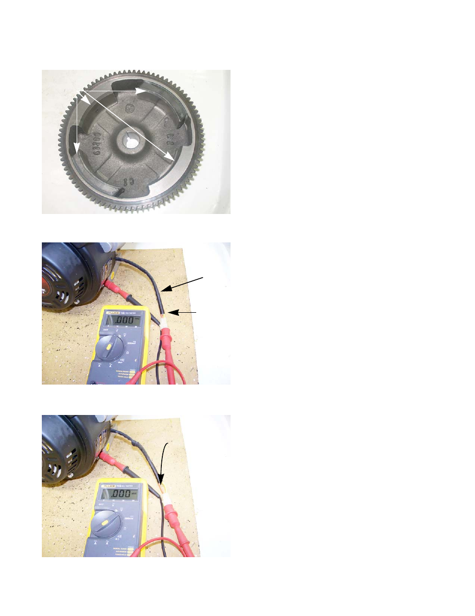
• Four magnets on the inside of the flywheel, refer to
figure 6.13, that rotate around a stator that is
mounted to the cylinder block. As the crankshaft
and flywheel rotate, the moving magnets induce a
charge in the stator.
• A rectifier: A set of diodes that turn the AC current
into DC current.
Testing
The charging system will produce AC and DC voltages.
The rectifier for the DC voltage is inside of the stator and is
not serviceable. To test the charging system:
1. Disconnect the charger harness.
2.
Connect the black (-) lead of a digital multimeter to a
good ground on the engine.
3.
Connect the red (+) lead of the multimeter to the yel-
low wire in the charger harness. See Figure 6.26.
4.
Set the multimeter to read AC voltage.
5.
Start the engine and run it at full throttle.
6.
The multimeter should read a voltage of 13 - 18Vac.
7.
Set the multimeter read DC voltage.
8.
Move the red (+) to the red wire of the charger har-
ness. See Figure 6.27.
9.
The multimeter should read 17 - 26Vdc.
10. If the results do not match what is listed above,
replace the stator.
Figure 6.25
Magnets
Figure 6.26
Charger harness
Yellow wire
Figure 6.27
Red wire