Pcv testing – Cub Cadet MTD 70 Series User Manual
Page 33
B
ASIC
T
ROUBLESHOOTING
27
PCV testing
The PCV valve is located in the valve cover and allows the crankcase pressure to escape.
Leakage and blockage are the two failure modes for a PCV system. Either mode will cause crankcase pressure
to build-up, though the effects of a blocked PCV are generally more dramatic. Increased case pressure will result in
oil entering the combustion chamber.
1.
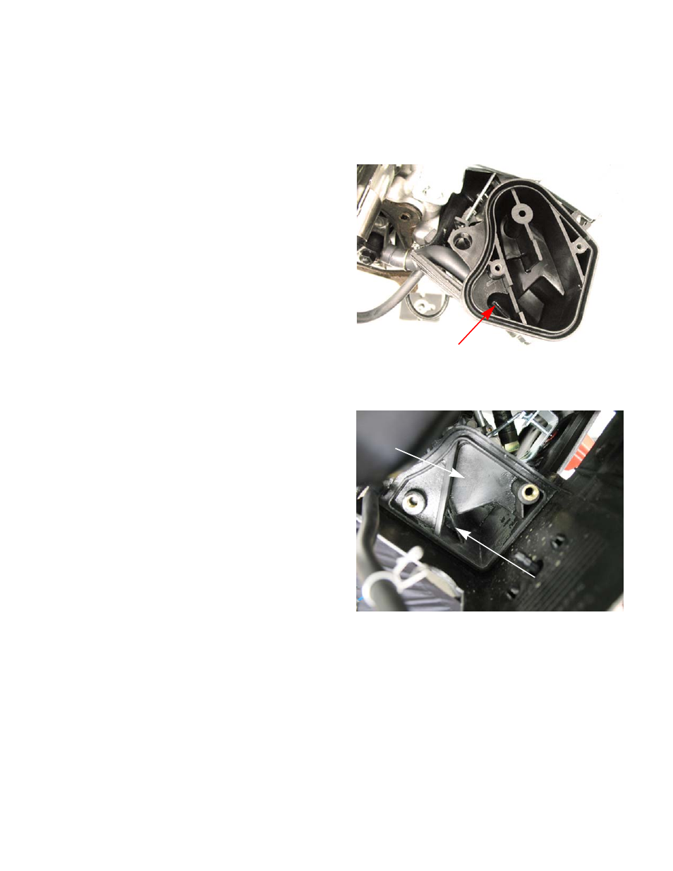
The PCV chamber is vented to the air filter through
a molded rubber hose. The rubber hose directs
crankcase fumes to a chamber within the air filter
housing. See Figure 2.3.
NOTE:
On snow blower engines the breather hose
connects to a chamber inside the lower half
of the heat box assembly. See Figure 2.4.
2.
When functioning properly, the PCV valve (Positive
Crankcase Ventilation) works with the inherent
pumping action of the piston in the bore to expel
pressure from the crankcase.
NOTE:
Normally, small engines run with slightly
negative case pressure. This case pressure
can be measured using a slack-tube water
manometer, or an electronic version of the
same tool. Less than (between -3 and -4”) (
-7.6 - 10.2cm) of water is a typical reading at
idle.
3.
An engine that fails to purge extra case pressure in
a controlled manner will build case pressure. The
pressure will find it’s own way out of the engine in
undesirable ways.
•
Oil will be forced by the rings and valve guides, being burnt in the combustion chamber.
•
The cause of this oil burning can be mistaken for a worn-out engine, if proper diagnosis (compression,
leak-down, and case pressure) is not performed.
4.
Experimentation by MTD’s Training and Education Department has revealed the following characteristics of
MTD engines:
•
A leaky PCV system will not build-up substantial case pressure.
•
A leaky PCV system will allow the engine to ingest contaminants through the system, accelerating engine
wear.
•
A blocked PCV system will allow crankcase pressure to build very rapidly. Noticeable oil fumes will be evi-
dent in the exhaust within several minutes of normal operation.
Figure 2.3
crankcase air chamber
Figure 2.4
Bottom of heat box
crankcase air chamber