COP-USA ASH56NVIR-L36S User Manual
Page 9
7
resistor to be connected in the circuit and other pan/tilts whose terminal resistors are opened so as to increase the
reliability of the system. Generally, the terminal resistor of the pan/tilt at the farthest end from the control circuit is
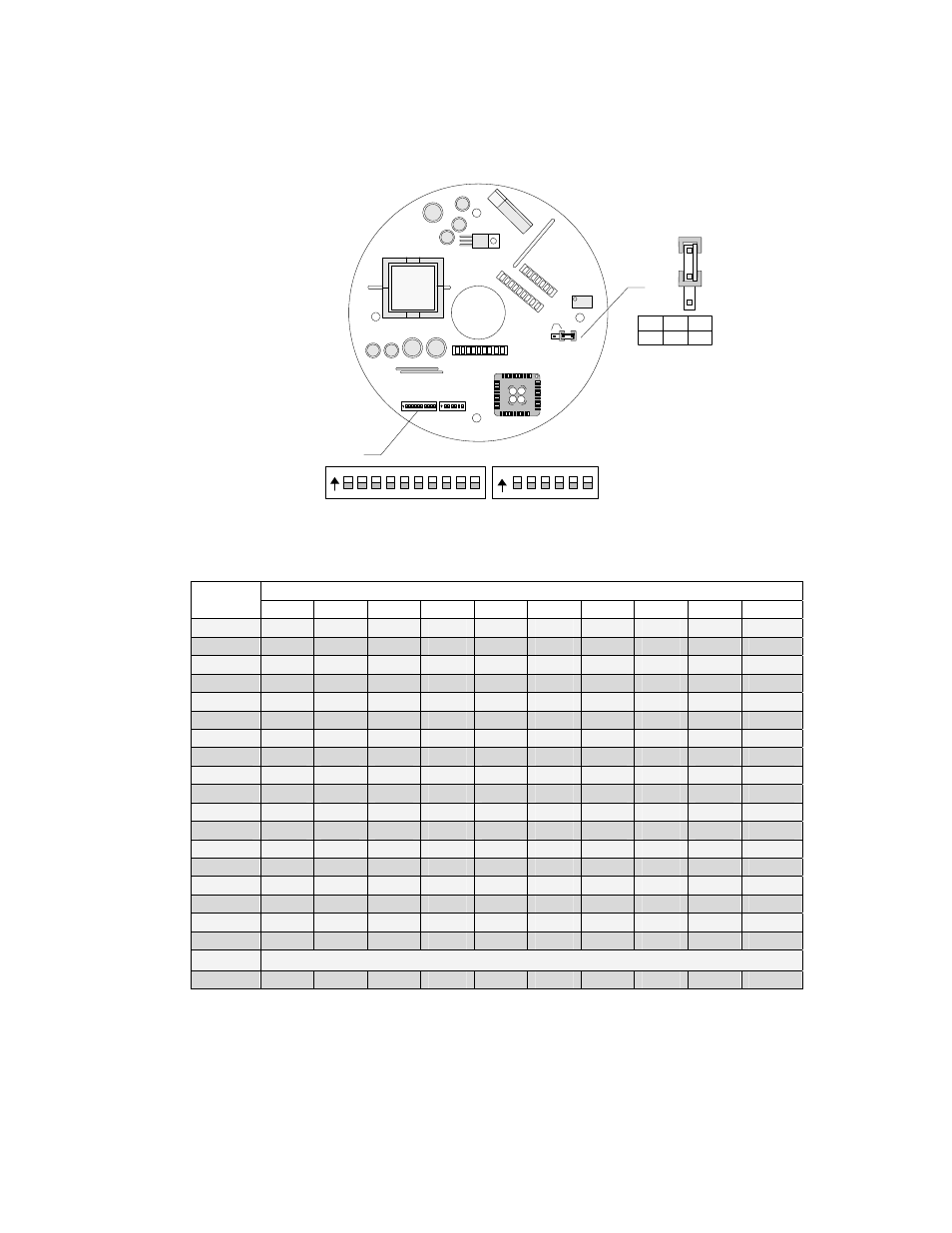
connected and all terminal resistors of other devices are opened.
JP1
JP1 1- 2 2- 3
120R ON OFF
ON DI P
1 2 3 4 5 6
ON DI P
1 2 3 4 5 6 7 8 9 10
3
2
1
Code
1
2
3
JP1
The jumper JP1 is the option switch of 120 Ω terminal resistor of the bus RS485.
2.Dip-Switch of Address:
Dome
Address
States of Dip-Switch
DIP-1 DIP-2 DIP-3
DIP-4
DIP-5
DIP-6
DIP-7
DIP-8 DIP-9 DIP-10
1
ON
OFF
OFF
OFF
OFF
OFF
OFF
OFF
OFF
OFF
2
OFF
ON
OFF
OFF
OFF
OFF
OFF
OFF
OFF
OFF
3
ON
ON
OFF
OFF
OFF
OFF
OFF
OFF
OFF
OFF
4
OFF
OFF
ON
OFF
OFF
OFF
OFF
OFF
OFF
OFF
5
ON
OFF
ON
OFF
OFF
OFF
OFF
OFF
OFF
OFF
6
OFF
ON
ON
OFF
OFF
OFF
OFF
OFF
OFF
OFF
7
ON
ON
ON
OFF
OFF
OFF
OFF
OFF
OFF
OFF
8
OFF
OFF
OFF
ON
OFF
OFF
OFF
OFF
OFF
OFF
9
ON
OFF
OFF
ON
OFF
OFF
OFF
OFF
OFF
OFF
10
OFF
ON
OFF
ON
OFF
OFF
OFF
OFF
OFF
OFF
11
ON
ON
OFF
ON
OFF
OFF
OFF
OFF
OFF
OFF
12
OFF
OFF
ON
ON
OFF
OFF
OFF
OFF
OFF
OFF
13
ON
OFF
ON
ON
OFF
OFF
OFF
OFF
OFF
OFF
14
OFF
ON
ON
ON
OFF
OFF
OFF
OFF
OFF
OFF
15
ON
ON
ON
ON
OFF
OFF
OFF
OFF
OFF
OFF
16
OFF
OFF
OFF
OFF
ON
OFF
OFF
OFF
OFF
OFF
17
ON
OFF
OFF
OFF
ON
OFF
OFF
OFF
OFF
OFF
18
OFF
ON
OFF
OFF
ON
OFF
OFF
OFF
OFF
OFF
…
…
1023
ON
ON
ON
ON
ON
ON
ON
ON
ON
ON
SW1 is used to set the addresses of the pan/tilt which has the range from 1 to 1023. From DIP-10 to DIP-1 it
corresponds to a binary number with 10 bits in which the highest bit is DIP-10 and the lowest bit is DIP-1. The
state ON for each bit means 1 while the state OFF means 0. The encodes of some addresses are as follows:
For example: