Fig. 3 fig. 4 – Checkline LMI-LMC User Manual
Page 6
6
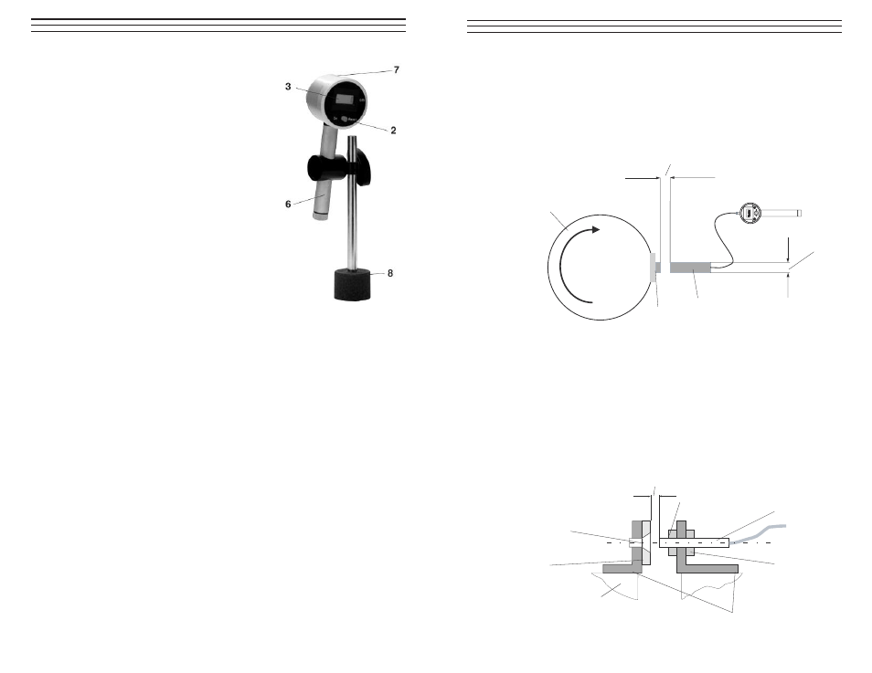
3.2 Setup
1. Place the magnetic base (8) at the desired
measuring point.
2. Insert the handle ( 6) of the electronic
yarn consumption meter in the holder of
the magnetic base.
3. Insert the material to be measured in the
groove of the filament guide ring (7) on
the rear side of the instrument. The
filament guide ring can be turned by
360°.
4. Adjust the electronic yarn consumption
meter in such a way that the angle of
material contact with the measuring
wheel is 120° minimum (see Fig. 2)
to eliminate material slip.
NOTE: The angle of material contact with the
measuring wheel must be at least 120°.
3.3 Measuring Procedure (refer to diagram on page 4)
1. On the LMC-S and LMC-I models, set the preselect switches
(9) and (10) to position 0, as shown in Fig. 4 on page 8.
2. Press the ON / RESET switch (2) to switch on the electronic
yarn consumption meter.
3. Switch on the knitting machine for the desired number of machine cycles.
The instrument now continuously measures the yarn consumption.
4. Switch off the knitting machine.
5. The display (3) now shows the measured length of yarn.
If a new yarn consumption measurement is necessary, repeat the
compete Measuring Procedure
NOTE: The electronic yarn consumption meter powers off automatically when the
measuring wheel on the rear of the instrument has not been moving for about
two minutes. The measured values are deleted.
7
4.0 M
EASURING
W
ITH
T
HE
LMC-S A
ND
LMI-S M
ODELS
4.1 Measuring with Manual Start /Stop
Follow the procedures outlined in section 3.0.
4.2 Measuring with Automatic Start/Stop Signal
The LMC-S and LMI-S models feature an adjustable counter for up to 99
cylinder revolutions of the knitting machine. The cylinder revolutions are
monitored by a magnetic switch.
To use this feature, the supplied magnet (12) must be mounted to the cylinder of
the knitting machine by using an M5 flat head bolt. The supplied magnetic
switch (11) is fitted to the stationary part of the knitting machine so that it is at
the same height as the magnet (12) (see Fig. 4 below). The switching distance
between the magnet and magnetic switch should be set to about 2mm with the
adjusting nut and lock nut of the magnetic switch.
Recommended switching distance approx. 2 mm
M5 thread
11 Magnetic switch
12 Magnet
Cylinder of circular
knitting machine
M5 flat head bolt
R
Recommended switching distance approx. 2 mm
Cylinder
Magnet
Magnetic switch
Adjusting nut
Lock nut
Mounting angle
Mounting Example
Fig. 3
Fig. 4