Checkline STM User Manual
Page 2
– 2 –
2.0 O
VERVIEW
2.1 Tension Range Markers
The STM-50 is equipped with two adjustable Tension Range Markers
that can be used to mark the upper and lower limits of the most
frequently used tension range
Scale
Instrument
Moveable Outer Ring
Measurement Pointer
Adjustable Markers
Fig. 1
Fig. 2
– 3 –
3.0 V
ERIFYING
C
ALIBRATION
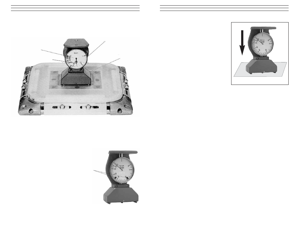
1. To confirm the calibration, place
the STM-50 on a glass plate and
press down (see Fig. 3).
2. The scale pointer should make
one full turn on the scale, from
zero to zero, when you press
down on the instrument. If it
does not, contact Electromatic
for assistance.
4.0 T
AKING
A M
EASUREMENT
1. Place the instrument on a flat surface and make sure that the Measurement
Pointer lines up with the zero position on the scale. If it does not, rotate the
Outer Ring carefully, moving the Zero Position Marker until it lines up
with the Measurement Pointer.
2. Place the STM-50 on the screen web as shown in Fig 1. Tap the screen
web lightly with your hands a few times to compensate for any mechanical
friction cause by the instrument. This will help to ensure repeatable
measurements.
3. Press down firmly on the STM-50. The Measurement Pointer will show
the screen tension directly in N/cm.
5.0 S
PECIFICATIONS
Tension Range
6–50 N/cm
Dimensions
3” x 1.8” x 4.5”
(75 x 46 x 115mm)
L x W x H
Weight (approx)
16.9 oz
(480 g)
Fig. 3
Smooth Glass Plate