Checkline DS-2000LED-OT User Manual
Page 8
– 8 –
6.0 A
DDITIONAL
O
PERAT
I
NG
I
NSTRUCTIONS
(OT M
ODEL
O
NLY
)
1. Press the
and
buttons simultaneously to switch between
internal and external trigger signal.
CAUTION: Do not use signals over 300,000 FPM Hz to trigger the device.
Display fields (see pages 3 and 4)
Influencing the input signal before the flash is generated
3
DELAY ms
Adjustment of delay time (in milliseconds) between
the internal trigger signaland the fl ash.
4
PHASE deg
Phase shift adjustment between the internal trigger
signal and the flash (in degrees, relative to the
frequency).
5
DIV
Pulse divider, maximum value 255.
6
OPT
Trigger signal edge selection
0 = positive edge
1 = negative edge
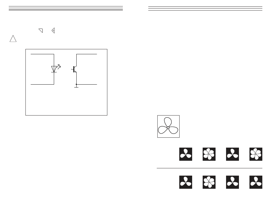
❚
rigger input
3 … 32V
BROWN
BLUE
Trigger output
max. 50mA
WHITE
BLACK
CAUTION
!
The trigger input is potential-free and is suitable for PNP
and NPN signals. A cable with plug, correspnding to
these iput jacks, is provided with the device.
Trigger Connection Assignment - Trigger Jack
– 13 –
10.0 DETERMINING AN OBJECT’S TRUE RPM
The strobe can be used as a digital tachometer to determine the true
RPM and/or the reciprocation rate of an object. This is done by visually
“freezing” the object’s movement and then reading the LCD display. As
with all stroboscopes, it is important to verify that this frozen image is
not a harmonic of the object’s actual rate.
Helpful Hints
■
Knowing the approximate rate of the object in advance gives you a
useful starting point.
■
If the object has a uniform shape, like a multi-blade fan or motor
shaft, you must give it an identifying mark (using paint or reflective
tape or equivalent) in order to differentiate its orientation.
■
A singular image always appears at exactly one half of the object’s
true RPM.
■
Mathematical harmonic techniques can be used to determine an
object’s true RPM if it is greater than the upper limit of the
stroboscope.See Example 3 on page 15.
Example 1 (Within Range):
This example shows why identifying marks are
important.
Suppose you want to determine the true RPM of this
fan. The only thing you know is that its speed is less
than 3,500 RPM. If you slowly decrease the flash rate
starting from 3,500 FPM, the following “frozen” images
appear:
Image No.:
1
2
3
4
Flash Rate:
3.300
1,650
1,100
916.6
Image No.:
5
6
7
8
Flash Rate:
825
733.3
660
550
M