Checkline DS-2000LED-OT User Manual
Page 7
– 7 –
4. If the flash frequency corresponds to the motion frequency, a static
image will be created. If the image does not appear static (motion-
less), adjust the flash frequency using the Adjustment Buttons as
indicated below
Increases the currently set value.
Speeds up when this button is held down.
Halves the currently set value.
Speeds up when this button is held down.
Doubles the currently set value.
Speeds up when this button is held down.
Lowers the currently set value.
Speeds up when this button is held down.
CAUTION:
Although the object may appear to be motionless, it is
still moving and should NEVER be touched.
5
The following functions are activated by simultaneously pressing
the buttons shown below:
+ = Reset to default settings
+
= Activate/Deactivate Button Lock.
Prevents current settings from being changed accidentally
5.1 Using Special Functions
PULS µs/PULS deg:
Flash duration. This function enables you to set the fl ash duration.
Using this function, you can influence the brightness and focus of
the object of observation. This adjustment can either bemade in
absolute form (microseconds) or in relative form (degrees).
DELAY ms
Adjustment of delay time between the internal trigger signal and
the flash (in milliseconds). Thisfunction enables you to set a fixed
delay time between the internal trigger signal and the flash.
Example: The position of observation can be adjusted extremely
precisely without altering the flash frequency. You can shift the
observation position within a motion cycle.
PHASE deg
Phase shift adjustment between the internal trigger signal and the
flash (in degrees, relative to the frequency). This function enables
you to set a fixed angle between the internal trigger signal and the
flash.
Example: The position of observation can be adjusted extremely
precisely without altering the flash frequency. You can shift the
observation position within a motion cycle.
CAUTION
!
– 14 –
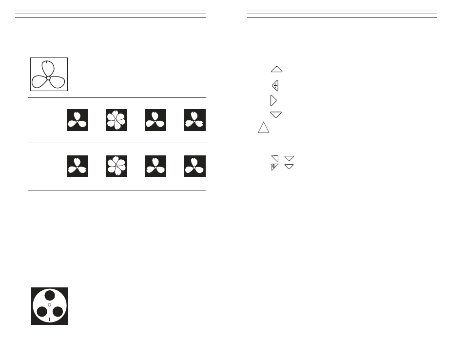
What is the actual rate of the fan? Images 1, 3, 5, 7, and 8 are all
“frozen,” so the rate could be taken as 3,300. 1,100, 825, 660 or 550.
Which is correct?
In order to determine the fan’s actual speed, a mark is
added to one of the blades and the test is run again.
Image No.:
1
2
3
4
Flash Rate:
3.300
1,650
1,100
916.6
Image No.:
5
6
7
8
Flash Rate:
825
733.3
660
550
Using the orientation mark, it is now clear that the images appearing at
3,300, 825 and 660 RPM are multiple-image harmonics. In each of these
cases, three identification marks appear. On the other hand, a singular
image appears at 1,100 and again at 550.
Here, only one mark appears. Recall that “a singular image always
appears at exactly one half of the object’s true RPM.” 550 is one half
of 1,100. Therefore, the rate of the fan must be 1,100 RPM.
Example 2: (Within Range No Mark Needed)
This example illustrates how the actual speed of an object can be deter-
mined without the use of an orientation mark—provided that the object
has a suitable shape.
Assume that the speed of this cam is known only to be
less than 7,000 RPM. Because it has a unique shape, it
does not need an identifying mark. As the flash rate is
lowered from 7,000, the following harmonic images
appear.
M
+
*
–
–
–