For series 20 & 21, For series 22 – California Faucets Builder Series Widespread Faucets User Manual
Page 2
Lift Knob
Hole Rod
Strap
Nut
Ball
Rod
Cone
Washers
Flat Rubber
Washer
Drain
Tailpiece
Rubber
Washer
Drain
Collar
Stopper
Drain
Rim
3
Nut
Brass
Nut
Connect faucet to water supply:
IMPORTANT: Flush supply lines of all
debris prior to connecting to lavatory
valve bodies. Debris remaining in the
line will damage valve bodies and
cause leaking. Failure to flush the
lines could result in voiding the warranty.
Install "P" trap:
-Connect your waste
"P" trap to the drain
tailpiece.
Fig. 4B
Fig. 5
Fig. 6
Fig. 7
Fig. 8
Ball Rod
Lift
Rod
Drain
Tailpiece
"P" Trap
(not supplied)
Angle Stop
(not supplied)
Valve
Body
Supply Riser
(not supplied)
2A
Spring
Clip
-Connect supply risers from the angle stops.
NOTE:
P-trap, angle stops,
and supply risers
are not supplied.
Eye-Hole
Eye-Hole
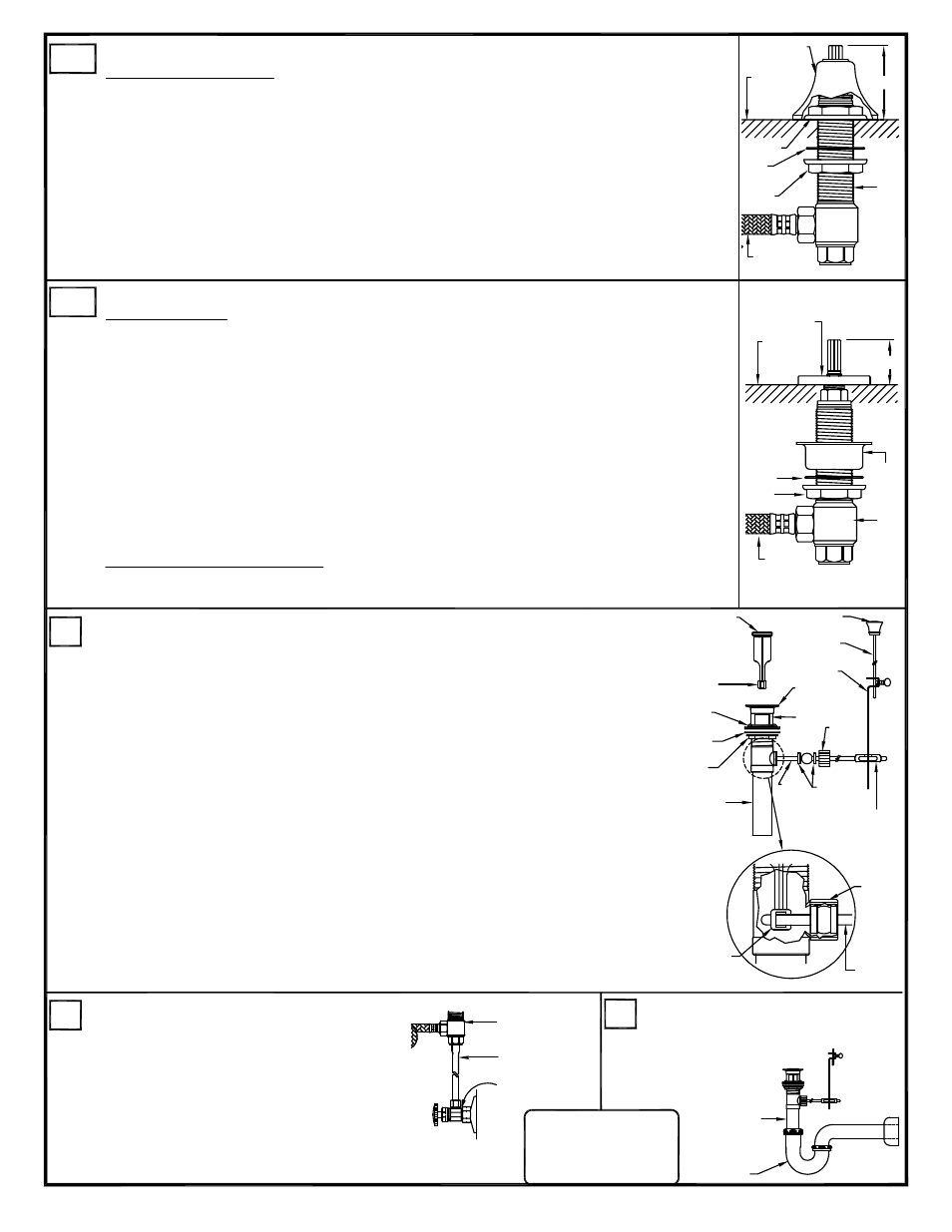
NOTE: Hot & cold valves are labeled: cold=blue & hot=red.
-Loosen handle set screws with Allen key provided. Remove handle, escutcheon and top nut.
Turn bottom nut with fiber washer down the valve until stops, (repeat for other valve).
-Insert valve through hole from below and install top nut, and adjust to proper
height. (See Fig. 4A), (repeat for other valve).
-Tighten the bottom nuts to secure the valves onto sink or countertop.
-Install trim parts escutcheons and handles and tighten handle set screws with allen key provided.
Reminder: Please retain Allen key as handles may require re-tightening with normal use.
-Attach flex lines between valves and spout tee. Hand tighten, then 1/4 to 1/2 turn more with
wrench (not supplied). Do not overtighten. (See Fig 1).
Install pop-up assembly.
-Separate drain collar from pop-up assembly.
-Apply silicon caulking to underside of drain collar. NOTE: Do not use
"Plumbers Putty" or any oil based sealants! Use of anything other than
silicon caulking will VOID the finish warranty.
-Insert drain body from underside through sink. Slowly screw on drain
collar, align with ball rod hole facing back wall, then gently pull down into
sink and firmly tighten brass nut from below.
-Remove tailpiece from drain body and apply teflon tape, approx. 3 to
5 wraps around threads and reinstall into bottom of drain body.
-Insert stopper in collar and hold with eye-hole facing back (See Fig. 5).
-Remove spring clip from ball rod.
-Remove nut and cone washers and slide onto end of ball rod.
-Insert ball rod into drain body below so short end of ball rod end fits
in stopper eye-hole. Snug ball rod nut (do not over tighten).
Ball rod must move up & down freely (See Fig. 5).
-Insert lift rod through top of spout and then through hole rod strap
underneath sink. Tighten thumb-screw of hole rod strap
against lift rod and connect to ball rod by gently pinching locking
spring clip and sliding one side of spring clip onto ball rod.
-Insert hole strap onto ball rod, then pinch spring clip together to fit on ball rod.
Ref. WSBLD2-INSTL
P2
NOTE: Hot & cold valves are labeled: cold=blue & hot=red.
-Loosen handle set screws with Allen key provided. Remove handle, escutcheon, and spacer
cup. Turn bottom nut with fiber washer down the valve until stops and place spacer cup with
flange up back onto the valve body, (repeat for other valve).
-Insert valve through hole from below and install the escutcheon and adjust to proper height,
(See Fig. 4B). Then place handle onto valve broach to verify correct clearance between handle
and escutcheon, (repeat for other valve).
-Align handle in desired position and tighten the bottom nut to secure the valve,
(repeat for other valve).
-Install handles and tighen handle set screws with Allen key provided.
Reminder: Please retain Allen key as handles may require re-tightening with normal use.
-Attach flex lines between valves and spout tee. Hand tighten, then 1/4 to 1/2 turn more with
wrench (not supplied). Do not overtighten. ( See Fig 1.)
Installation Note for series: #22
The trims to these products do not require a top nut to be installed on the valve,
the escutcheon takes the place of the top nut, (See Fig. 4B)
2B
Install valve bodies:
For series 20 & 21
4
5
Fig. 4A
2 3/8"
Sink/
Countertop
Escutcheon
Top Nut
Fiber
Washer
Flex
Line
Bottom
Nut
Valve
1 1/8"
Sink/
Countertop
Fiber
Washer
Bottom
Nut
Flex
Line
Valve
Escutcheon
Spacer
Cup
Install valve bodies:
For series 22