Brookfield UL Adapter User Manual
Page 3
Brookfield Engineering Laboratories Inc.
- 3 -
Operating Instructions M/91-080-I1003
Fluid
Recommended
Recommended
Note
Temperature
Fluid
Tubing
-10
°
C to 15
°
C 50/50
Ethylene
Fluran
R, 2
Do Not Use Gum
Glycol/Water
1
Rubber Tubing With
This Fluid
15
°
C to 65
°
C Water
Gum
Rubber
or Fluran
R
65
°
C to 100
°
C Silicone
Oil
3
Fluran
R
Do Not Use Gum
Rubber Tubing With
This Fluid
R
Fluran is a Registered Trademark of Norton Co.
1. Use only laboratory grade ethylene glycol. Do not use automobile anti-
freeze which contains materials that can damage the equipment.
2. Fluran tubing (5/16" ID) and clamps are offered in a kit, part # ULA-45A.
3. Do not use high viscosity oil. Recommended is 50 centipoise.
6. Add the sample to the chamber. Immerse the spindle into the chamber with the extension link and coupling
nut attached, then thread the water jacket to the locating channel assembly. Once that is done, thread the
coupling nut to the viscometer. This way the spindle is not hanging from the viscometer and it prevents
a mess with the sample. You can hook the extension link to the lip of the chamber to prevent the spindle
from dropping too far down.
7. Level the viscometer. General operating procedures for making viscosity measurements are described in
the viscometer operating instruction manual.
8. UL Adapter spindle factors are shown on page 4. The factor is used to calculate viscosity when using Dial
Reading or Model DV-I Viscometers. Model DV-I+/II/II+ Viscometers and DV-III/DV-III+ Rheometers
calculate the viscosity value automatically when the “cP display mode” is selected. The spindle entry
code for the UL Adapter is 00.
Notes
•
Maximum recommended viscosity for measurement with the UL Adapter is 2000 cP (mPa•s). If viscosity
exceeds 2000 cP, the material being measured may be too viscous to immerse the spindle/tube, and damage
to internal parts of the viscometer may result.
•
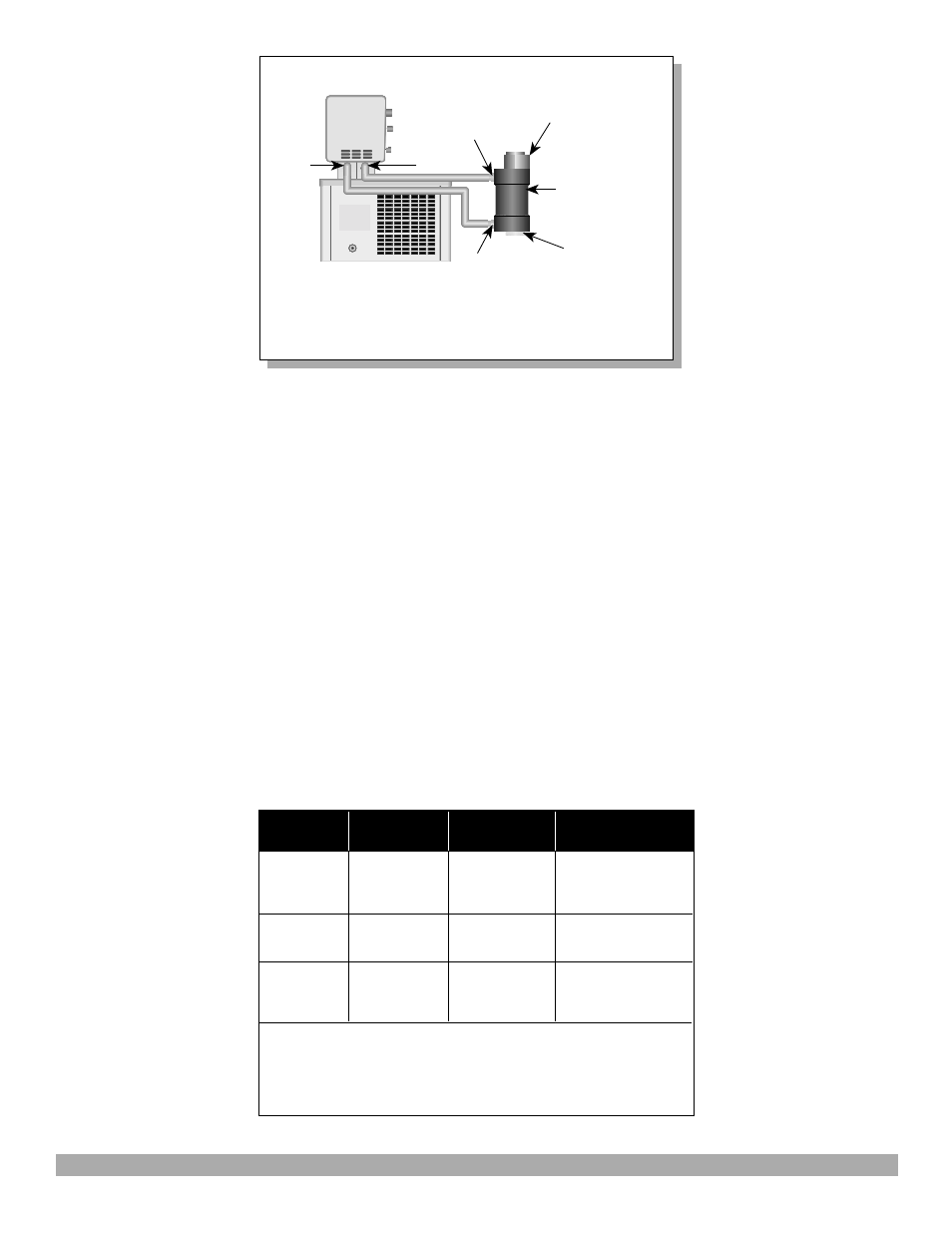
For tubing and fluid recommendations when using a Constant Temperature Bath, refer to the table below:
Figure 4: ULA-40Y water jacket connections
PUMP
INLET
PUMP
OUTLET
Water
Bath
Bath
Inlet
Bath
Outlet
ULA-40Y
Water Jacket
Jacket
Outlet
Jacket
Inlet
Sample
Tube
ULA-34
Tube End
Cap
Temp.
Bath