Module physical interface, Module spi interfaces, Aw900mspi user’s manual – AvaLAN Wireless AW900mSPI-10 User Manual
Page 6
AW900mSPI
User’s Manual
PAGE 6
Technical support (650) 384-0000
www.avalanwireless.com
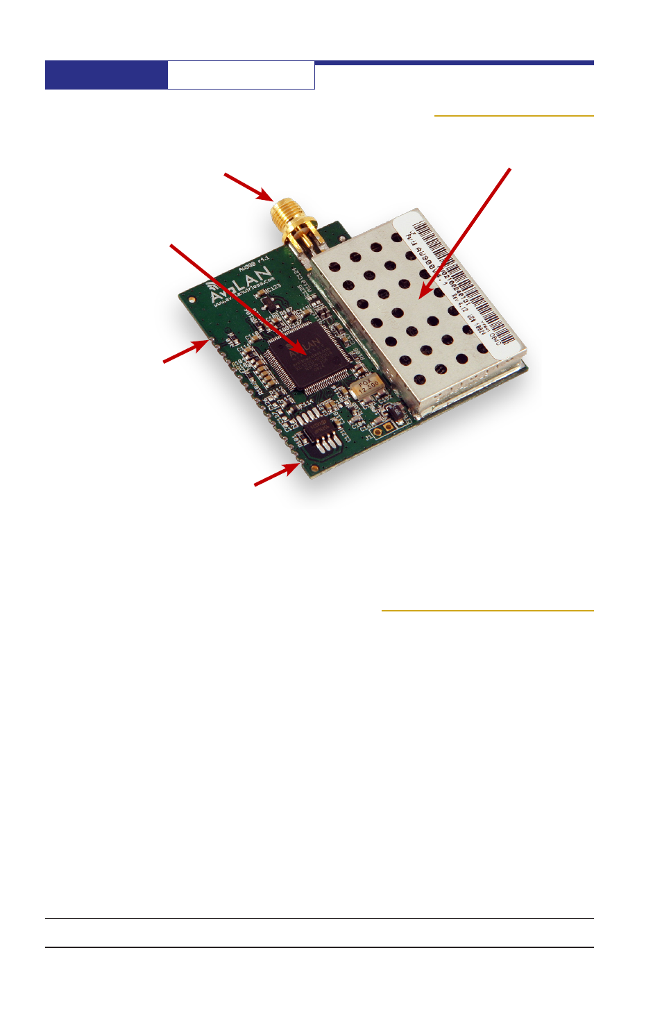
Module Physical Interface
Pin 1
Pin 17
RF Antenna
RPSMA
AvaLAN
XC1220 Chip
Module SPI Interfaces
Serial Peripheral Interface (SPI) is a full duplex synchronus serial interface that al-
lows data to be shifted in and out of the AvaLAN Baseband Processor (XC1220) 8 bits
at a time, most significant bit first.
Each SPI requires 4 pins to be physically connected:
• SCK – Serial bit shift clock (provided by master SPI)
• MISO – Master In Slave Out
• MOSI – Master Out Slave In
• CS – Active low Chip Select
There are two SPI interfaces on the AW900mSPI. The first is a master SPI (SPI0),
operating LEDs and DIP switches. SPI0’s connections are pins 3-6. The second is a
slave SPI (SPI1) for management of the radio link, statistics, firmware upgrading,
and data transfers. SPI1’s connections are on pins 12-15.
RF Section