Aw900mspi user’s manual, Data commands – AvaLAN Wireless AW900mSPI-10 User Manual
Page 22
AW900mSPI
User’s Manual
PAGE 22
Technical support (650) 384-0000
www.avalanwireless.com
Byte 32
DP15
DP14
DP13
DP12
DP11
DP10
DP9
DP8
DP is the 16-bit integer number of data points in the spectrum scan. The value will
depend upon the frequency step size specified in Byte1. The next 4 data bytes will
be repeated DP times.
b7
b6
b5
b4
b3
b2
b1
b0
Byte 33
OFS7
OFS6
OFS5
OFS4
OFS3
OFS2
OFS1
OFS0
Byte 34
OFS15
OFS14
OFS13
OFS12
OFS11
OFS10
OFS9
OFS8
Byte 35
PEAK7
PEAK6
PEAK5
PEAK4
PEAK3
PEAK2
PEAK1
PEAK0
Byte 36
AVG7
AVG6
AVG5
AVG4
AVG3
AVG2
AVG1
AVG0
...
Repeat DP times to read all the spectrum data
OFS is the 16-bit integer Index value for this data point. The range of this index is
0 to (128 − Frequency Step Size). For example, with a step size of 1, the maximum
value of OFS is 127, but with a step size of 8, the maximum value is 120.
PEAK is an 8-bit integer representing the peak power detected at each frequency.
AVG is an 8-bit integer representing the average power detected at each
frequency.
Both the PEAK and AVG readings are a logarithmic scale, with a value of zero cor-
responding to -100 dBm and a value of 255 corresponding to -15 dBm:
Power in dBm = − (100 − ((Sample Value) / 3))
Please be aware that this scale is approximate. Linearity is poor above -20 dBm or
below -90 dBm.
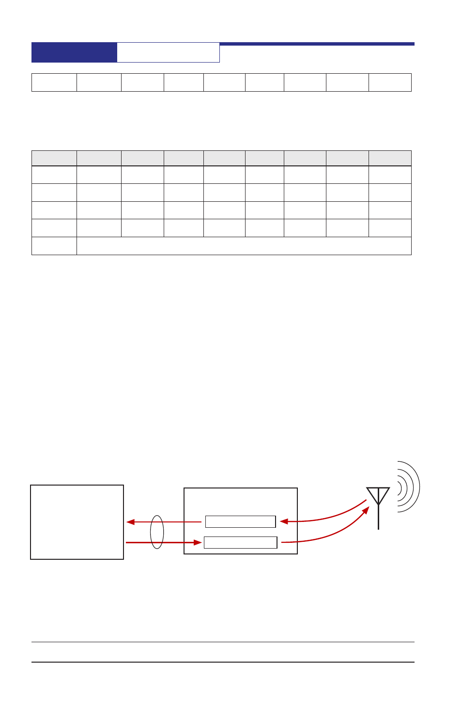
XC1220
5 KB Receive FIFO
8 KB Transmit FIFO
Host
Microcontroller
SPI or
UART
Data Commands
The data commands are used to transfer data between the XC1220 and the host
microcontroller that is intended for RF transmission.