Implementation block diagrams, Suggested spi user implementation – AvaLAN Wireless AW900mSPI-10 User Manual
Page 29
PAGE 29
Technical support (650) 384-0000
www.avalanwireless.com
AW900mSPI
User’s Manual
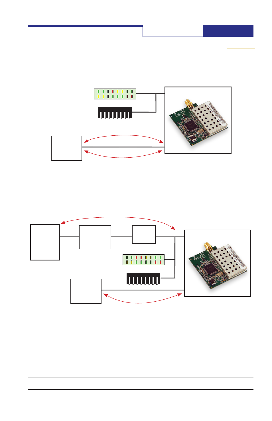
Suggested UART User Implementation:
Diagnostic LEDs
Configuration DIPs
AvaLAN AW900mSPI
PC
Single Port
USB to UART
Chip
UART
to SPI
Chip
USB
UART 0
SPI 0
UART data at 9600 to 115,200 bps
configuration data and statistics
User’s
Embedded
µController
(Recommended
but not required)
Suggested SPI User Implementation:
Diagnostic LEDs
Configuration DIPs
AvaLAN AW900mSPI
SPI 0
SPI data at 7 Mbps
configuration data and statistics
User’s
Embedded
µController
SPI 1
(Recommended
but not required)
Note that if you are using the AW900mSPI in UART mode, you may wish to include
a USB interface to SPI0 similar to that implemented in the Evaluation Board. This
would allow you to modify the configuration, to read back operating statistics and
to perform spectrum analysis. If those capabilities are not needed, then the cost
and space can be avoided.
Implementation Block Diagrams