Evaluation board physical interface, Aw900mspi user’s manual – AvaLAN Wireless AW900mSPI-10 User Manual
Page 30
AW900mSPI
User’s Manual
PAGE 30
Technical support (650) 384-0000
www.avalanwireless.com
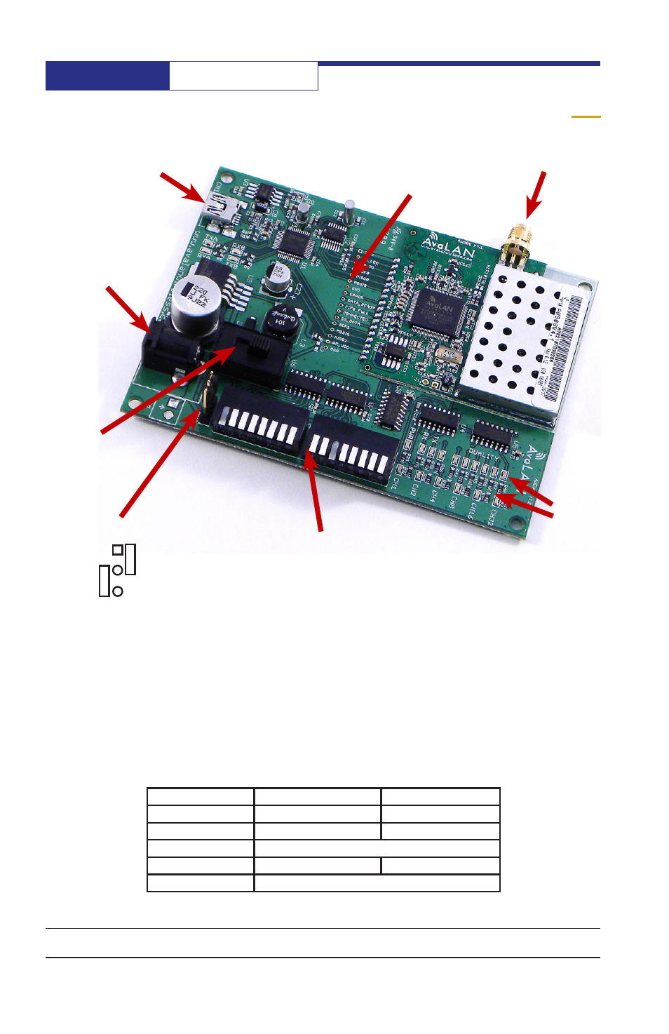
Evaluation Board Physical Interface
USB Connector
P5 Power
Connector
RF Antenna
RPSMA
LEDs
DIP Switches
1 at left
through 16 at right
Power Switch
(on to left)
Power Jumper
Connect
1&2
for USB
Connect
2&3
for P5
Module Interface
Probe Points
Note that the power for the USB chips is always provided by the USB port and is not
otherwise switched. The power for the radio and associated parts is controlled by
the power switch and may come from either the USB port or the P5 power connec-
tor, depending on the placement of the power jumper. If powered by USB, make
sure that the port you are using will support attachment of a "high power" device. If
in doubt or if you experience functionality issues, use the external 12 VDC adapter
provided in the EVAL kit.
The probe points and LEDs are labeled on the board. The DIP switch settings:
DIP Switch Number
Off
On
1
Subscriber Unit
Access Point
2
UART Firmware Active
SPI Firmware Active
5-8
RF Channel Selection (binary coded, LSB on Left)
11
Normal Mode
"Ping Pong" Test Mode
All Others
Not used
1
2
3