Adaptive Technologies 2X4-UE46A-VWD User Manual
Page 6
© 2013 Adaptive Technologies Group, Signal Hill, CA 90755 USA (562) 424-1100 Rev.00-02/18/13
Step 1: Mount Video Frame to Wall
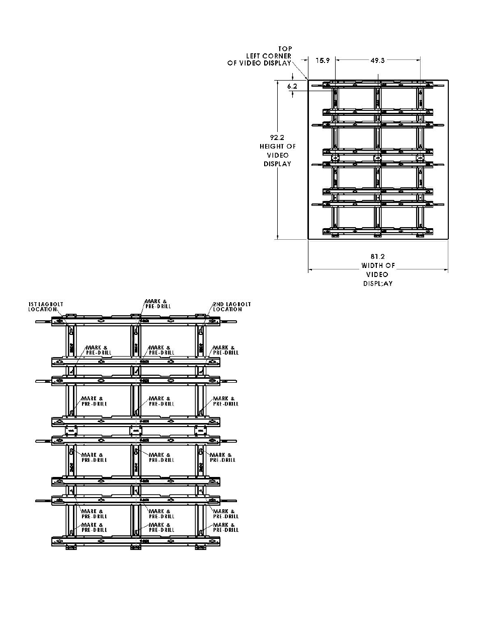
Scribe a horizontal line on the wall showing the exact
location of where the top edge corner of the upper left
monitor will be. Measure down 6.2” (157.5mm) from that
line and scribe another horizontal line showing where the
horizontal location of the first adjustable lag bolt will be
(Figure 1).
Scribe a vertical line showing where the top left side of
the upper monitor will be. Measure to the right 15.9”
(403.9mm) and scribe another vertical line showing where
the vertical location of the first adjustable lag bolts
(Figure 1). Mark the intersection of the vertical and
horizontal lines.
Measure 49.3” (1252.2mm) to the right for the location of
the second adjustable lag bolt. Use a long level to make
sure the second location is horizontally aligned and
leveled to the first lag bolt location (Figure 1). Mark the
second lag bolt location.
Pre-drill the marked lag bolt locations using a 3/16” or
5mm drill bit. Install the first and second adjustable lag
bolts to the pre-drilled holes until the hex part of the bolt is
flush to the wall. A deep socket wrench maybe required.
Step 2:
Hang the frame from the top keyholes to the adjustable lag
bolts (Two people minimum required). Install the provided
hex nut and flat washer over the adjustable lag bolts, level
frame then tighten the hex nuts.
Use the frame as a template to mark the other locations of
the adjustable lag bolts (18 plcs). Use three (3) per V-
channel, two keyholes and the center hole (Figure 2).
Loosen and remove the hex nut and flat washer securing the
frame to the wall then place the frame back on the floor. Pre-
drill marked holes using the 3/16” or 5mm drill bit then install
the other adjustable lag bolts until the hex part of the bolt is
flush to the wall (Figure 2).
Hang the upper frame back onto the adjustable lag bolts
mounted on the wall. Install hex nut and flat washer then
snugly tighten hex nuts. DO NOT TIGTHEN permanently
until the entire video frame is installed and adjusted (Figure
3).
Step 3:
Use a long level to plumb the frame by rotating the adjustable
lag bolts on the V-channels using the provided adjustment
wrench starting from one side of the frame. Rotate counter
clockwise to pull the frame forward and clockwise to push the
Figure 1
Figure 2