Adaptive Technologies 1X4-X462-VWD User Manual
Hovertrack, Assembly instruction guide
© 2011 Adaptive Technologies Group, Signal Hill, CA 90755 USA (562) 424-1100 Rev.00-07/11
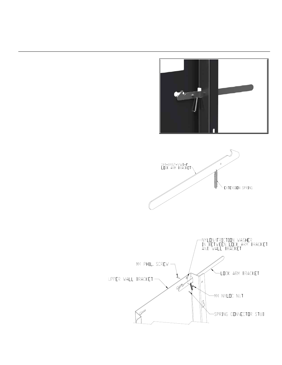
Figure 1
Locking Arm
HoverTrack
®
Series
1X4-X462-VWD
Assembly Instruction Guide
Important: Assembling video displays is a serious endeavor that requires
experienced professionals. Improperly assembled equipment can result in
property damage, injury, death and/or liability to the installing contractor. Do
not proceed if any part of the installation is in doubt.
Follow these instructions for the most efficient and safest assembly results.
Package Contents:
1 pc
1X4-X462-VWD-A 3 high wall bracket (Upper fixture)
1 pc
1X4-X462-VWD-B Single wall bracket (Lower fixture)
4 pcs
1X4-X462-VWD-C Locking bracket
1 pc
1X4-X462-VWD-E Link Plate bracket
4 pcs
Extension Spring
4 pcs
Spring connector stud (already attached to bracket)
4 pcs
Nylon/friction washer, white
4 pcs
Phil. Pan head screw, M4x16mm long
4 pcs
Nylock Nut, M4
Step 1:
Check hardware to make sure it is complete to assemble the parts. Refer
to package contents.
Step 2: Assemble Locking Arm
Hook one end of the extension spring to the small hole on the locking
bracket (Figure 1).
Step 3:
Insert the locking bracket with spring into the rectangular slot of the wall
bracket with the open hook facing up. Align the hole of the locking arm
with the hole on the wall bracket. Place a nylon/friction washer in
between the locking arm and the wall bracket then secure with the
provided M4x16mm long screw and M4 nylock nut. Make sure the head
of the screw is on the outer side of the wall bracket (Figure 2).
Step 4:
Connect the other end of the extension spring
to the spring stud connector attached to the wall
bracket (See main illustration).
Step 5:
Check that locking arm can pivot easily; loosen
M4 screw and nut if it is too tight.
Step 6:
Repeat step 2 to 5 for the other locking arms.
Step 7:
Refer to product Installation guide.
Figure 2