Som 7 si, Installation, 1 mounting – STIEBEL ELTRON SOM 7 SI User Manual
Page 4: 2 electrical connection
SOM 7 SI
© 08042 som_7_si.monen.ind
d
|
4
VBus
®
display
pushbutton
can fuse 4A
cable conduits with strain
relief
cover
1
2
S1
S2
S3
3
4
5
6
Temp. Sensor Pt1000
L
N
R1
N
R2
N
20
19
18
17
16
15
S4
7
8
14
13
12
DE - 45527 Hattingen
DeltaSol BS Plus
2 (1) A 115
2
V~
(1) A 115 V~
R1
R2
T4A
115 V~
CU 72060171 01
UL 60730-1A:2002
CSA E60730.1:2002
VBus
9 10
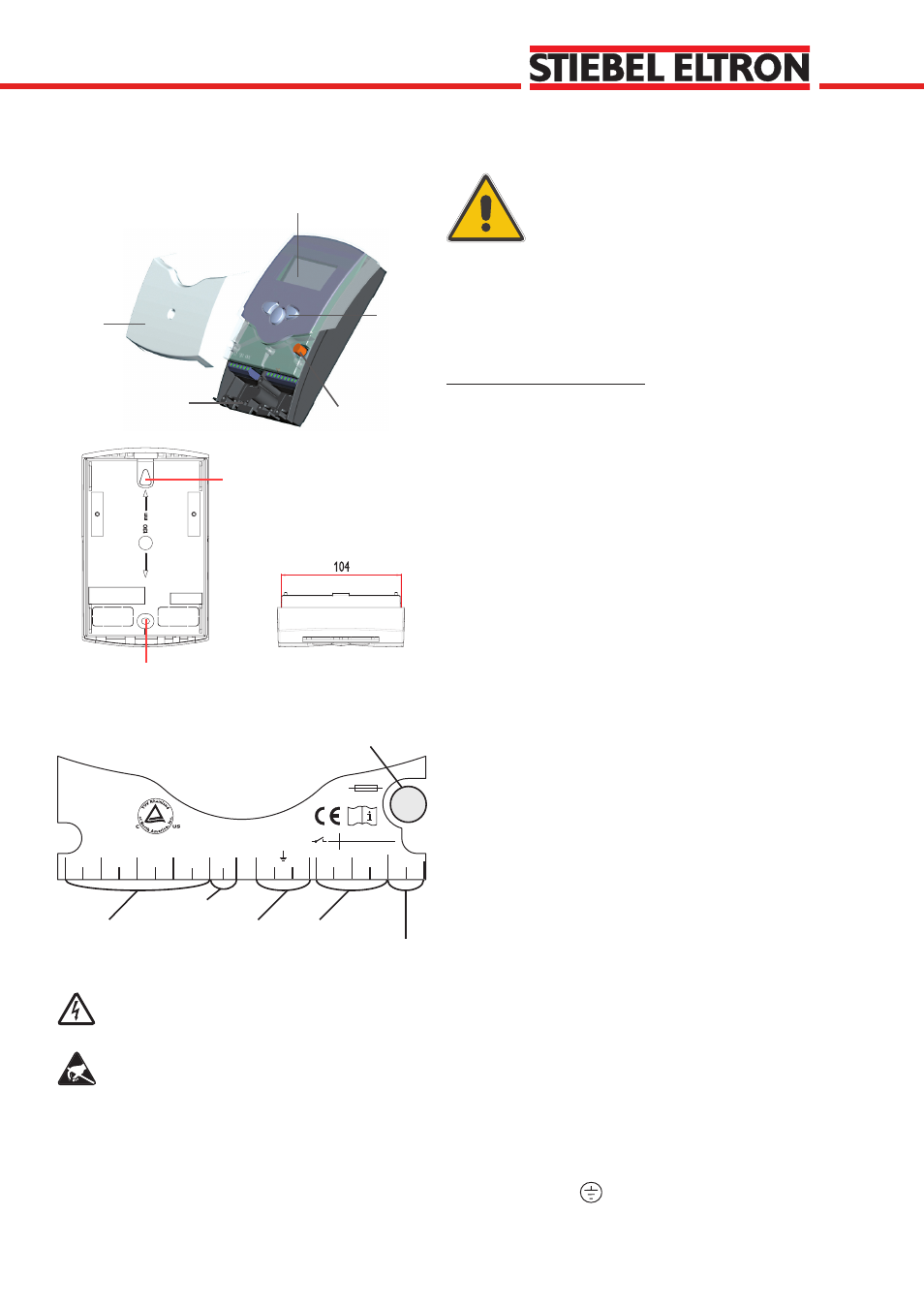
1.1 Mounting
1. Installation
1.2 Electrical connection
The power supply to the controller must only be made by
an external power supply switch and the line voltage must
be 120 VAC (50/60 Hz). Flexible lines are to be fixed at the
housing by enclosed strain relief supports and screws.
The controller is equipped with 2 standard relays, to which
the consumers (pumps, valves etc.) can be connected:
• Relay 1
18 = conductor R1
17 = neutral conductor N
13 = ground clamp
• Relay 2
16 = conductor R2
15 = neutral conductor N
14 = ground clamp
The temperature sensors (S1 up to S4) will be
connected to the following terminals independently of the
polarity:
1 / 2 = Sensor 1 (e.g. Sensor collector 1)
3 / 4 = Sensor 2 (e.g. Sensor tank 1)
5 / 6 = Sensor 3 (e.g. Sensor collector 2)
7 / 8 = Sensor 4 (e.g. Sensor tank 2)
The power supply is effected to the clamps:
19 = Neutral Conductor N
20 = Line Conductor L
12 = Ground Clamp
net clamps
fuse
consumer clamps
Sensor clamp
fastening
fixing
ground clamp
Electrostatic discharge can lead to damages of elec-
tronic components!
Dangerous voltage on contact!
The unit is designed for indoor installation only. It is not
suitable for installation in hazardous locations and should not
be sited near to any electromagnetic field. The controller
must installed in accordance with all electrical regulations.
These regulations vary from region to region. Please contact
the appropriate agency in your area if unclear on this.
Wall Mounting Instructions
1. Unscrew the cross-recessed screw of the cover and
remove it from the housing.
2. Mark the upper fastening point on the wall and mount
the enclosed dowel and screw.
3. Hang up the housing at the upper fastening point and
mark the lower fastening point on the wall. The distance
between the 2 mounting holes is 130 mm.
4. Fasten the housing at its lower point..
Warning!
Switch-off power supply before
opening the housing.