Som 7 si – STIEBEL ELTRON SOM 7 SI User Manual
Page 11
© 08042 som_7_si.monen.ind
d
11
|
SOM 7 SI
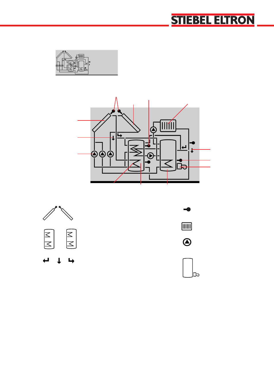
The system screen (active system scheme) shows the
schemes selected on the controller. It consists of several
system component symbols, which are - depending on the
current status of the system - either flashing, permanently
shown or hidden.
Sensors
Collector 1
Collector 2
Pumps
Heating circuit
Sensor
Additional symbol for
operation of the burner
Valve
Tank
Tank heat-exchanger
Tank 2 or afterheating (with
an additional symbol)
upper sensor tank
Valve
Pump
3-way-valve
The flow direction or the
current breaking capacity
is always shown.
Heating circuit
Tanks 1 and 2
with heat-exchanger
Afterheating
with burner symbol
Temperature sensor
2.2.3 System screen
System Screen only
Collectors
with collector sensor
Constantly green:
Normal operation
Red/green blinking: Power-up phase
Manual operation
Red blinking:
Sensor defect
(sensor symbol is quickly blinking)
2.3 Blinking codes
2.3.2 LED blinking codes
2.3.1 System screen blinking codes
• Pumps are blinking during starting phase
• Sensors are blinking when their value is being displayed in
the indication channel.
• Sensors are quickly blinking in case of sensor defect.
Burner symbol is blinking if after-heating is activated
•