Som 7 si, Symptom possible cause and remedies list, Troublesooting tips – STIEBEL ELTRON SOM 7 SI User Manual
Page 25: F ω °f ω
© 08042 som_7_si.monen.ind
d
25
|
SOM 7 SI
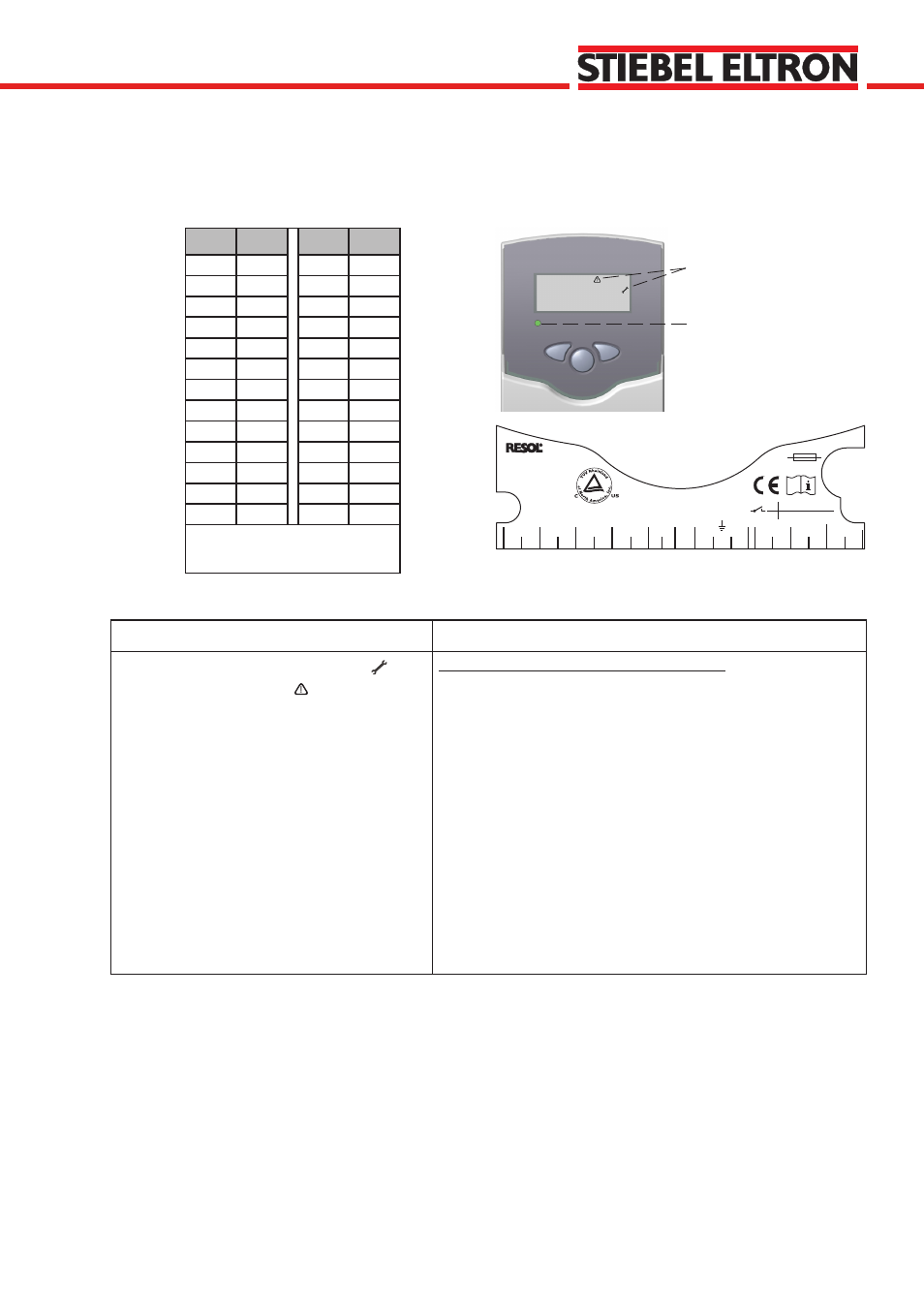
5. Troublesooting Tips
If a malfunction occurs, it will be indicated on the display of
the controller:
Operating control lamp
Warning symbol
1
2
S1
S2
S3
3
4
5
6
Temp. Sensor Pt1000
L
N
R1
N
R2
N
20
19
18
17
16
15
S4
7
8
14
13
12
DE - 45527 Hattingen
DeltaSol BS Plus
2 (1) A 115
2
V~
(1) A 115 V~
R1
R2
T4A
115 V~
CU 72060171 01
UL 60730-1A:2002
CSA E60730.1:2002
VBus
9 10
°F
Ω
°F
Ω
14
961
131
1213
23
980
140
1232
32
1000
149
1252
41
1019
158
1271
50
1039
167
1290
59
1058
176
1309
68
1078
185
1328
77
1097
194
1347
86
1117
203
1366
95
1136
212
1385
104
1155
221
1404
113
1175
230
1423
122
1194
239
1442
Resistance values of the
Pt1000-sensors
Symptom
Possible Cause and Remedies List
Operating control lamp flashes red. The
symbol is displayed and the
symbol is flashing.
The indication channel of the relevent sensor
displays 888.8 instead of the temperature.
SOM unit is sensing an open circuit condition.
Measure the resistance between the two terminals to which
1.
the relevent sensor is attached. If it measures infinite resis-
tance continue to step 2. If it measures a resistance within
range of the above chart, call for service.
Disconnect the sensor wire from the terminals and measure
2.
the resistance between the two wires. If it still measures infi-
nite resistance continue to step 3. If it measures a resistance
within range of the above chart, there is a problem with the
connection from the sensor wire to the terminal.
This problem lies either with the sensor or the wire/connec-
3.
tions. In order to determine whether the problem lies with
the sensor itself, the sensor must be disconnected from any
extension wire and its resistance must be measured. If, when
the sensor is disconnected, the resistance is measured to be
within the values of the resistance chart the problem is with
the extension wire/connections.