Software configuration – Steffes 5140 Simplified Installation Guide User Manual
Page 8
15
SOFTWARE CONFIGURATION
If access to Configuration Menu times out, the 15
amp circuit breaker must be powered off and back
on to re-enter the menu.
The Steffes Comfort Plus Hydronic system has a Configuration
Menu, which allows it to be customized to the power company
and consumers needs. This menu can be accessed on start-
up and allows configuration settings to be easily adjusted.
Accessing the Configuration Menu
Step 1
Energize the system. Access to the Configuration
Menu is allowed for the first two (2) minutes of
operation. If the system has been energized for
over two (2) minutes, it must be powered off and
back on again.
Step 2
Press and release the M button until the faceplate
displays CONF.
Step 3
Press the up arrow once and the faceplate will
display C000. The display will flash between
C000 and the corresponding configuration value.
Step 4
If necessary, edit the configuration by pressing and
holding the M button while using the up or the down
arrow button to change the value.
Step 5
Once the value is correct, release the buttons and
press the up arrow button to go to the next
configuration (C001, C002, etc.).
Step 6
Repeat steps 4 through 5 until all configuration
settings have been adjusted to the desired values.
Step 7
Once configured, use the down arrow to leave the
Configuration Menu.
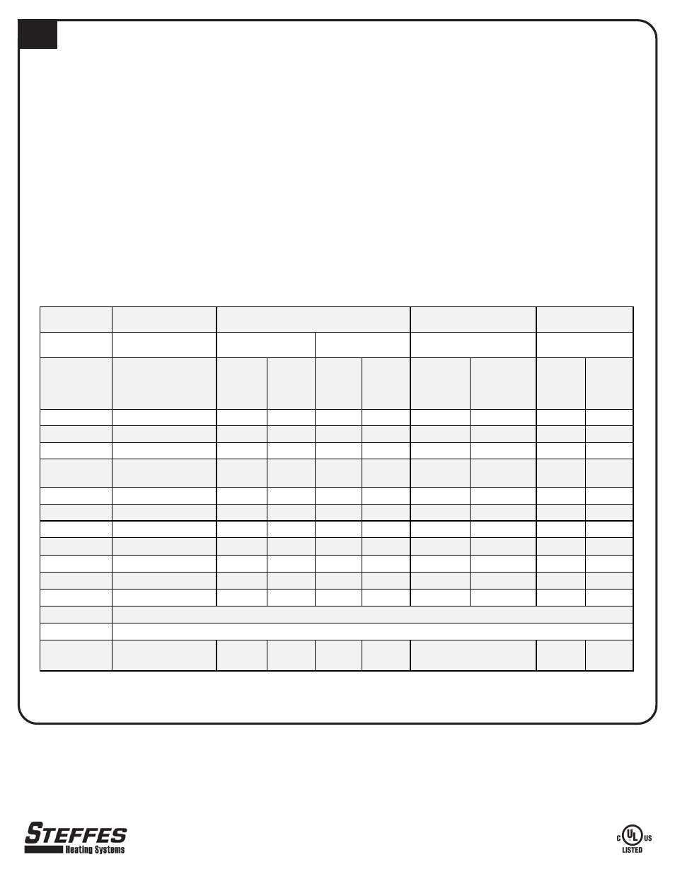
In most applications only a few, if any, configuration changes will be necessary. Following is a description of the configuration
settings and their functions:
Part No. 1200284-4
3050 Hwy 22 North w Dickinson, ND 58601-9413 w www.steffes.com
Power Line Carrier
(PLC) Peak Control
Configuration
Number
Outdoor
Sensor
(Factory
Default)
No
Outdoor
Sensor
Outdoor
Sensor
No
Outdoor
Sensor
Outdoor
Sensor
No Outdoor
Sensor
Outdoor
Sensor
No
Outdoor
Sensor
C000
5
5
6
5
6
5
6
5
6
C001
50°F
50°F
50°F
50°F
50°F
50°F
50°F
50°F
50°F
C002
10°F
10°F
10°F
10°F
10°F
10°F
10°F
10°F
10°F
C003
Match to the Channel
Selected at PLC
0
0
0
0
0
0
0
0
C004
8
9
8
9
8
13
12
9
8
C005
0
1
1
0
0
0
0
0
0
C006
2
2
2
2
2
2
2
2
2
C007
30
30
30
30
30
30
30
30
30
C008
5°F
5°F
5°F
5°F
5°F
5°F
5°F
5°F
5°F
C009
5°F
5°F
5°F
5°F
5°F
5°F
5°F
5°F
5°F
C010
90°F
90°F
90°F
90°F
90°F
90°F
90°F
90°F
90°F
C011
C012
C013 - C021
Refer to the Time Clock
Installation Instructions
* Risk of high temperature water. Can cause property damage. Improper water temperature settings can result in damage to the floor
covering. Make sure the maximum and minimum water temperatures (C011 and C012) are appropriate for the application
APPLICATION DEPENDENT *
APPLICATION DEPENDENT *
Low Voltage Direct
Wire Peak Control
Peak Switch Closed
for Charging
Peak Switch Open
for Charging
Line Voltage Peak
Control
Time Clock Module Peak
Control