Heating element installation, Air channel installation, Brick core temperature sensor(s) installation – Steffes 5140 Simplified Installation Guide User Manual
Page 2
4
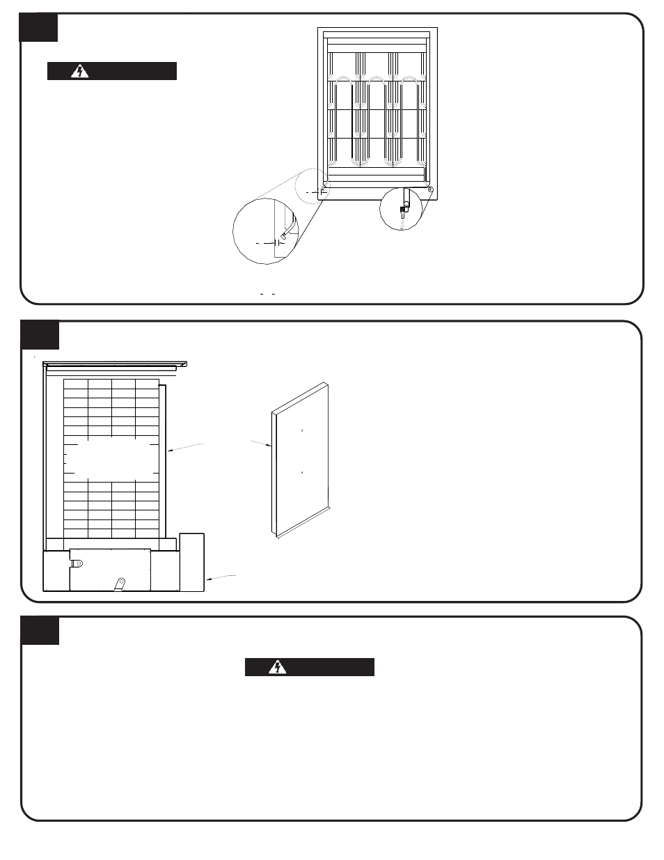
HEATING ELEMENT INSTALLATION
1. Insert heating elements
between brick layers until
element ends embed into side
cutouts of brick cavity.
Elements MUST be installed
with threaded screw tabs on
wire connection terminals
pointing forward and down.
2. Remove painted panel from
electrical compartment and
locate the installation hard-
ware package.
3. Connect wiring harnesses to
heating elements using
screws in hardware package.
Install screws with heads up
and thread pointing down.
Tighten screws to 14 in·lbs.
5
AIR CHANNEL INSTALLATION
1. Install air channel with air deflectors (arrow
shaped pieces) facing inward. Place bottom of air
channel in first.
2. Lower insulation blankets back into position, one
at a time. Tuck sides into edges, corners and
around exposed portions of heating elements.
3. Install galvanized front panel. Slide bottom edge
inside lower lip of brick cavity. Top rests on
outside of cavity.
4. Check non-insulated element connections to make
sure they do not come within 1/2" of any surface.
6
BRICK CORE TEMPERATURE SENSOR(S) INSTALLATION
Risk of improper operation. Proper installation of the brick core temperature sensor(s) is critical to the
operation of the Comfort Plus Hydronic system. Read and follow installation instructions carefully.
1. Remove screw(s) by temperature sensor hole(s) in galvanized front panel.
2. Insert temperature sensor(s) through hole(s). Sensor(s) must pass through blanket insulation and into brick core.
3. Install screw(s) into galvanized front panel to hold sensor(s) and provide electrical ground connection.
4. Inspect sensor wiring for possible short circuiting hazards.
5. Install painted front panel.
NOTE: Models 5130 and 5140 have an upper and a lower temperature sensor. Each sensor is marked for proper installation.
BRICK
CORE
SIDE VIEW
Outlet
Inlet
Electrical
Panel
Front Air
Channel
3
4
"
3
4
"
Required Clearance
Between Element Termination and
Metal Panels is
1
2
" (
3
4
" Nominal).
Element
Connection
WARNING
WARNING
WARNING
WARNING
WARNING
WARNING
WARNING
WARNING
WARNING
WARNING
HAZARDOUS VOLTAGE: Risk of
electric shock, injury or death.
DO NOT remove electrical panel
cover while system is energized.
Elements MUST be positioned
properly to avoid short circuiting
them against any surfaces
within system.
Use care when making
connections to avoid element
damage.