Low voltage peak control connections, Low voltage outdoor sensor connections, Low voltage room thermostat wiring – Steffes 5140 Simplified Installation Guide User Manual
Page 6: Single zone application, Relay, Outdoor, Inputs peak, Dry contact peak control switch, The y1/y2 jumper must be installed, Outd oor outd oor
13
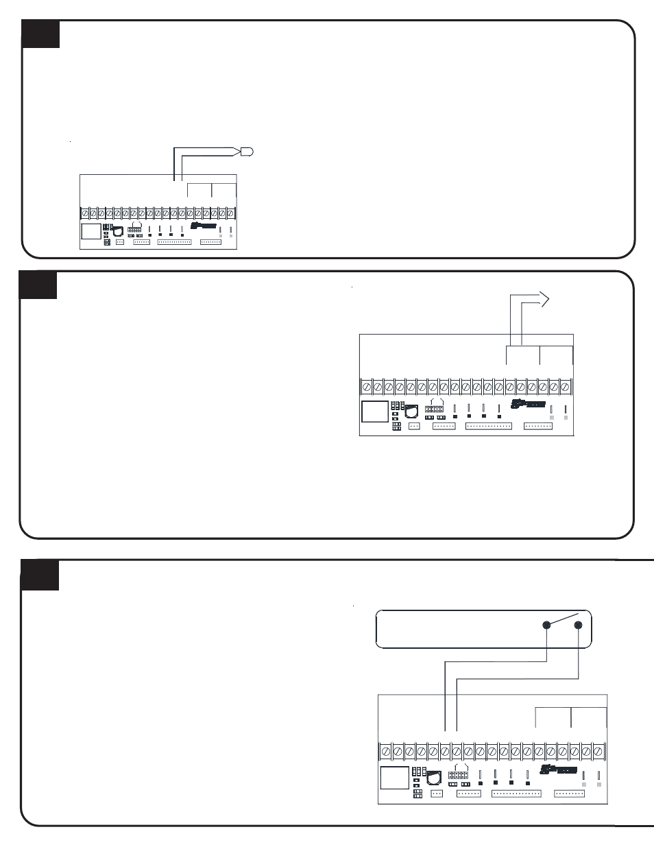
LOW VOLTAGE PEAK CONTROL CONNECTIONS
1. Route low voltage circuit from the peak control device
to the terminal block.
2. Connect field wiring to positions RP and P.
12
LOW VOLTAGE OUTDOOR SENSOR CONNECTIONS
The outdoor temperature sensor can be installed by wiring it
directly to the system or to the Steffes power line carrier
(PLC) system, if utilized.
Direct Wired:
1. Mount outdoor sensor in a location where it can accu-
rately sense outdoor temperature.
2. Route low voltage wire from outdoor sensor to electrical
compartment:
Seal external wall openings.
Outdoor sensor lead can be extended to 250 ft.
Unshielded Class II (thermostat) wire can be used
provided it is segregated from any line voltage wiring.
3. Connect outdoor sensor wires to Outdoor positions on
low voltage terminal block.
If connecting to the Steffes power line carrier
system, follow the installation instructions in the
PLC systems Owners and Installers Guide.
Outdoor sensor wire MUST NOT be combined with
other control wiring in a multi-conductor cable.
If utilizing a Steffes Time Clock Module or Power
Line Carrier control, refer to the installation
instructions provided with the device.
Low Voltage Terminal Block Coding
RP = Peak Control Input Common
P = Peak Control Input
AP = Anticipated Peak (Pre-Peak) Control Input
COM = Peak Control Output Common
NC = Peak Control Output (Closed for Charge)
NO = Peak Control Output (Closed for Control)
LOW VOLTAGE ROOM THERMOSTAT WIRING
14
SINGLE ZONE APPLICATION
A 24 VAC thermostat must be used (digital recommended).
1. Disconnect power to Comfort Plus Hydronic system.
Route low voltage thermostat wire to the system.
2. Insulate thermostat wire wall opening if necessary.
3. Attach thermostat. When using a mechanical thermostat
or thermostat with anticipator, resistor kit #1190015 must
be installed to ensure proper operation.
4. Route low voltage wire into electrical compartment to
low voltage terminal block.
5. Install electrical panel cover.
P8
P9
Aux.
COM
NC
AP
NO
Relay
Outdoor Sensor
O
W/
Y1
AUX
Y2 G
Ou
tdoo
r
Ou
tdoo
r
Y2
R
H/E
2
Y1
C
O
2
2
RP P
R
C
P1
P11
D3
D7
D5
W
E
Y
1
Y
2
Wa
te
r
Air
P6
D1
P5
Blower
J3
J1
J2
J4
D2
To Control Board
P3
C
Blower
Speed
A
B
J5
J6
C3
D
P4
P2
Inputs
Peak
P7
LV Circuit Board
Comfort Plus
To Control Board
P10
Fid 2
RLY1
D4
D6
R2
R1
P9
Aux.
COM
NC
AP
NO
Relay
P8
O
W/
Y1
AUX
Y2 G
Outdoor
Outdoor
Y2
R
H/E
2
Y1
C
O
2
2
RP P
R
C
P1
Inputs
Peak
P7
LV Circuit Board
Comfort Plus
To Control Board
P10
Fid 2
RLY1
D4
D6
R2
R1
P11
D3
D7
D5
W
E
Y
1
Y
2
Wat
e
r
Ai
r
P6
D1
P5
Blower
J3
J1
J2
J4
D2
To Control Board
P3
C
Blower
Speed
A
B
J5
J6
C3
D
P4
P2
Dry Contact Peak
Control Switch
P9
Aux.
CO
M
NC
AP
NO
Relay
Hydronic Heat Thermostat, Zone
Valve, End Switch, or Pump Control
The Y1/Y2 Jumper
must be installed
P8
O
W/
Y1
AUX
Y2 G
Outd
oor
Outd
oor
Y2
R
H/E
2
Y1
C
O
2
2
RP P
R
C
P7
LV Circuit Board
Comfort Plus
To Control Board
P10
Fid 2
RLY1
D4
D6
R2
R1
P11
D3
D7
D5
W
E
Y
1
Y
2
Wa
te
r
Ai
r
P6
D1
P5
Blower
J3
J1
J2
J4
D2
To Control Board
P3
C
Blower
Speed
A
B
J5
J6
C3
D
P4
P2
Inputs
Peak
P1