Line voltage electrical connections, Junction box installation, Air conditioner/heat pump interface – Steffes 5140 Simplified Installation Guide User Manual
Page 3: Warning, Circuit phasing connections, Circuit breakers
7
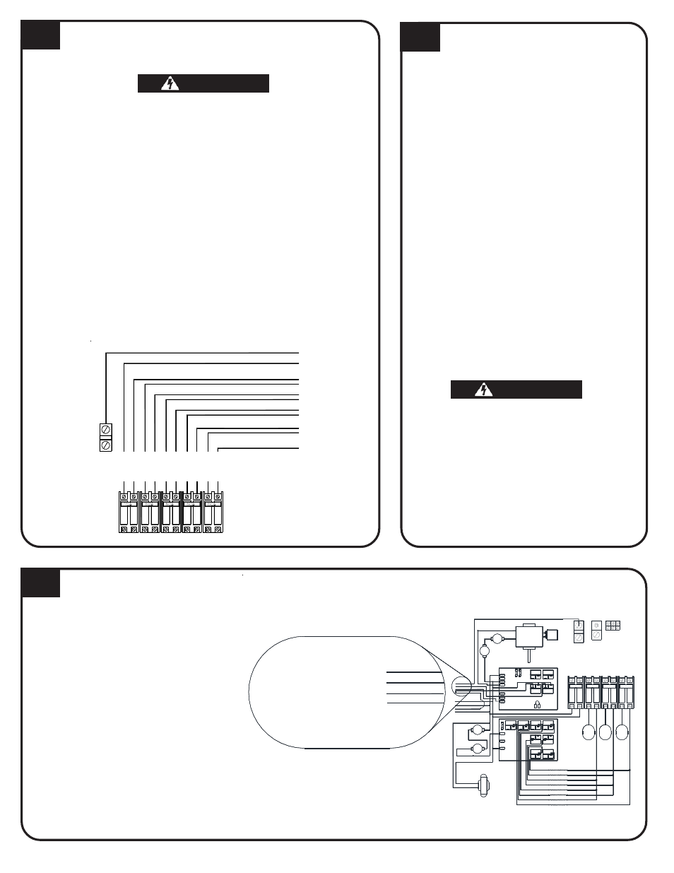
LINE VOLTAGE ELECTRICAL
CONNECTIONS
HAZARDOUS VOLTAGE: Risk of electric shock, injury or
death. Do not energize the Comfort Plus Hydronic system
until installation is complete.
1. Route all line voltage wires through knockout(s) and into electrical
panel.
2. Make proper field wiring connections.
To ensure proper operation and safety, all line voltage cir-
cuits must be segregated from low voltage wiring.
To reduce electromagnetic fields associated with electrical
circuits and to avoid induced voltage on sensors and elec-
tronic devices, the circuit phases MUST be alternated as
shown below.
DO NOT install any wiring in the line voltage compartment of
the Comfort Plus Hydronic system unless it is rated for line
voltage.
CIRCUIT PHASING CONNECTIONS
9
JUNCTION BOX INSTALLATION
1. Attach the factory supplied junction
box to the left side of the Comfort
Plus Hydronic system.
2. Make connections to the primary loop
pump and air handler pump inside
this junction box. The red and white
wires connect to the primary loop
pump and the black and white wires
connect to the air handler pump. The
maximum connected amperage on
either of these circuits is 1.2 amps.
3 . Attach the junction box cover using
the screws provided.
If NOT utilizing the optional Static Heat Recovery Unit, the orange wire can be used to power a secondary pump.
8
AIR CONDITIONER/HEAT
PUMP INTERFACE
The Air Handler (Order #1302100) is an optional
device used to interface the Comfort Plus
Hydronic with a ducted heating or cooling
system such as a heat pump or air conditioner.
The Air Handler includes a plenum assembly,
supply air blower, water coil, air filter, wiring
harness, and hardware kit. When the Comfort
Plus Hydronic system receives a heat call from
the room thermostat, it energizes the supply
blower and the Air Handler's zone pump.
The Air Handler can be interfaced with a
standard heat pump system and will provide
comfort modulation. The system will monitor
the outlet air temperature and modulate in heat
from the Comfort Plus Hydronic as needed to
maintain the desired output air temperature.
The maximum coil size the Air Handler can
accommodate through the front access is 20"
(W) x 22" (H) x 21 3/16" (D). The inner dimen-
sions of the A-coil area are 21 3/16" (W) x 24 1/
4" (H) x 21 3/16" (D). If installing a coil larger
than the access dimensions, the coil must be
placed into the Air Handler during assembly.
Risk of fire. Any one ducting system
MUST NOT contain more than one air
handling (blower) system. If the applica-
tion requires multiple Comfort Plus
heating systems or it is necessary to
have multiple air handlers share the
same ductwork, you MUST contact
Steffes Corporation. There are special
installation requirements that MUST be
performed in an application such as this.
LI
NE
2
LI
NE
1
LI
NE
2
LI
NE
1
LI
NE
1
LI
NE
2
LI
NE
1
LI
NE
1
LI
NE
2
THIS MUST BE A 120/240V OR 120V/208V CIRCUIT
NEUTRAL CONNECTION FOR CONTROL CIRCUIT
T
o
S
e
rv
ice
(Breaker) P
anel
(MODEL 5130 and 5140 ONLY)
CHARGE CIRCUIT #4
CONTROLS CIRCUIT
CHARGE CIRCUIT #1
CHARGE CIRCUIT #2
CHARGE CIRCUIT #3
Circuit Breakers
NEUTRAL
LI
NE
2
LUG
COM
COM
BLACK
BLACK/YELLOW
CORE
LIMIT
COM
1/4 Amp
L1
COM
NO
COM
COM
NO
NO
NO
RED
BLUE/WHITE
BLUE/BLACK
ORANGE
ORANGE
DAMPER
RESISTER
RESISTOR
SHRU
LOOP PUMP
PRIMARY
BL
AC
K
BL
U
E
RE
D
COM.
WHITE
250 °
BLUE
BLAC
K/
Y
E
L
L
OW
RED
WHITE/BLACK
BLOWER
L2 240
L2 120
NO
NO
COM
COM
NO
NO
1/4 Amp
5 Amp
225 °
N.C.
AUTO
RESET
N.C.
RESET
MANUAL
EXCHANGER
LIMITS
HIGH
BLACK
Cap.
4uf
CORE BLOWER
NEUTRAL LUG
C
IRCU
IT
#
2
C
IRCU
IT
#
3
CH
A
R
G
E
C
IRCU
IT
#
1
CH
A
R
G
E
C
IRC
UI
T
CO
NT
RO
L
S
B
L
OWER
S/
CH
A
R
G
E
60A
60A
15A
60A
CONTROL CIRCUIT
Element
Element
Element
1,8
Relays
2,4,6
Relays
3,5,7
Relays
To
To
To
ELEMENT 1
ELEMENT 2
ELEMENT 3
ELEMENT 4
ELEMENT 5
ELEMENT 6
ELEMENT 7
ELEMENT 8
BOARD
EXPANSION
#1
GROUND
LUGS
L1
OR
WHITE
ORANGE
BLACK
COM
COM
HEATING ELEMENTS
Element 2
Element 1
Element 3
Element 4
NO
NO
75VA
240v 24v
TRANSFORMER
Element 7
Element 5
Element 6
Element 8
BLACK/YELLOW
LIMIT
WHITE/BLACK
CORE
L2 240
COM
COM
NO
NO
L2 120
RED
Red & White To
Primary Loop Pump
(Max 1.2 AMPS)
Black & White To Air
Handler Pump (Max 1.2 AMPS)
WHITE
OR
These wires are located in the lower left
corner of the electrical compartment.
75° C or higher for field connections of this device.
Use copper or aluminum conductors rated at
Wiring Diagram 240/208 Volt
5120 Line Voltage
WHITE/BLACK
RED
BLACK
WARNING
WARNING
WARNING
WARNING
WARNING
WARNING
WARNING
WARNING
WARNING
WARNING