Steffes HPB22 Troubleshooting Guide User Manual
Page 6
Page 4
Heat Pump Booster
Function: Air Delivery
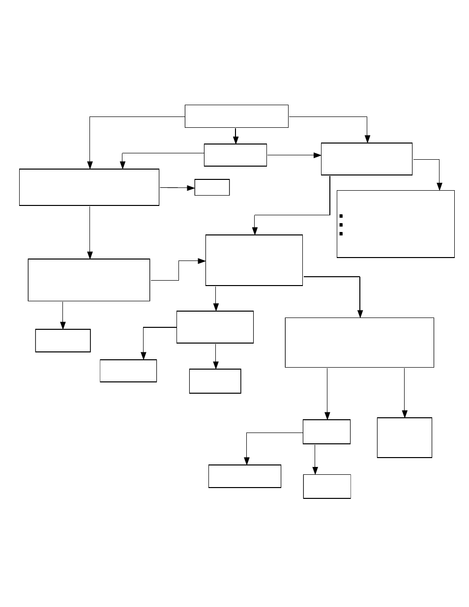
Problem: Cool discharge air
Before starting any of the procedure below, check voltage on load side of all HPB circuit
breakers. Check for 24 VAC between each of the low voltage fuses the "C" position on the
charge control circuit board's terminal block..
Blower delivers cool
discharge air.
Initiate a Stage I heat call.
Make sure the duct sensor (52) is
positioned properly and check field wiring.
With duct sensor (52) disconnected
at interface board (21), jumper the
red and black terminal block
positions. Watch for damper to open.
Ok
Cold Stage One
Does the charging system work
correctly? Refer to the Theory of
Operation in the Appendix of the
Owner's Manual.
Cold All Stages
Disconnect the yellow wire
from the damper motor (22).
Initiate a heat call, check
voltage between the yellow
wire and the red wire.
Refer to the appropriate
core charging sections of
this troubleshooting guide.
No
Yes
Check voltage between
the yellow wire and
the blue wire.
Are the sensors on the duct
sensor (52) and the air
discharge controller (45) open.
24 VAC
0 VAC
Replace the interface
board (21).
Replace the damper
motor (22).
24 VAC
0 VAC
Check unit
wiring.
Replace
appropriate
sensors.
No
Yes
Fix unit
wiring.
Replace the interface
board (21).
Correct
Incorrect
Damper doesn't
open
Replace duct
sensor (52).
Damper opens
Repair
Not Ok
Page 5
Blower delivers cool
discharge air.
Initiate a Stage I heat call.
Make sure the duct sensor is positioned
properly and check field wiring.
With duct sensor disconnected at
interface board, jumper the red and
black terminal block positions. Watch
for damper to open.
Ok
Cold Stage One Only
Does the charging system
work correctly? Refer to
the Theory of Operation.
Cold All Stages
Disconnect the red wire from
the damper motor. Initiate a
heat call, check voltage
between the yellow wire and
the red wire.
Refer to the appropriate core
charging sections:
Unit Undercharges
Unit Overcharges on Warm Days
Unit Will Not Charge (Unit has no
charge) or Control Board Lights
are Off
Check voltage between
the yellow wire and
the blue wire.
COLD ALL STAGES: Are both of the
sensors on the air discharge controller open?
COLD STAGE ONE ONLY: Are both of the
sensors on the duct sensor open?
24 VAC
Replace the
interface board.
Replace the
damper motor.
24 VAC
0 VAC
Check unit
wiring.
Replace air
discharge
controller or
duct sensor.
Yes
Fix unit
wiring.
Replace the interface
board.
Correct
Incorrect
Damper
doesn't
open
Replace duct
sensor.
Damper opens
Repair
Iniate emergency
heat call.
Not Ok
Uncertain
No/Uncertain
Now Warm
Still Cold
0 VAC
No
Yes