Steffes HPB22 Troubleshooting Guide User Manual
Page 3
Page 1
Heat Pump Booster
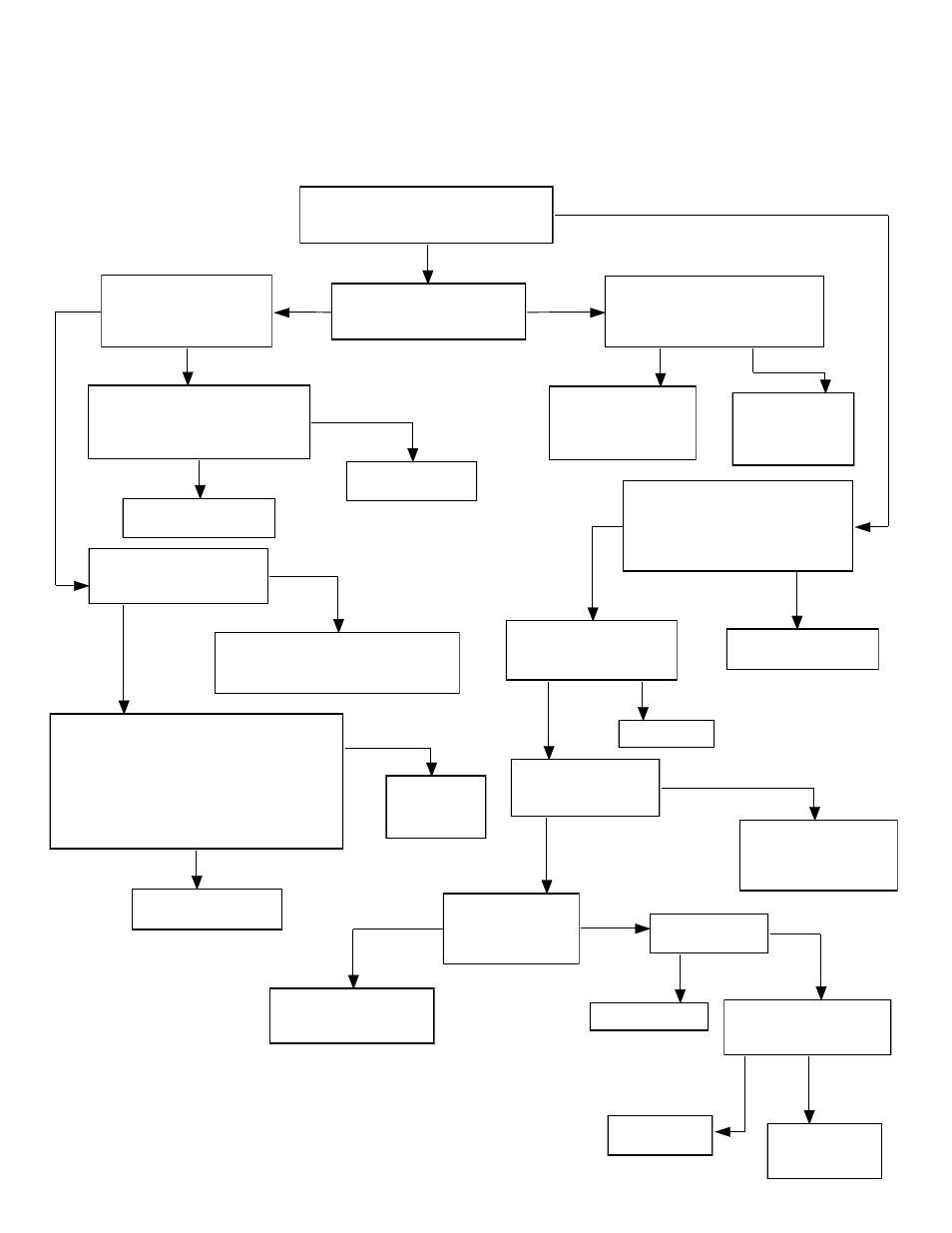
Function: Core Charging
Problem: Unit will not charge (Unit has no core charge) or Control Board lights are off.
Before starting any of the procedures below, check voltage on load side of all HPB circuit breakers and
check low voltage fuses on charge control circuit board. Place unit in off-peak mode.
Check utility switch and HPB off-peak
light on charge control circuit board
(51) for proper operation.
Check "Outdoor Temperature
Sensor" lights on charge
control circuit board (51).
Check "ETS CHARGING"
indicator light on charge
control circuit board (51).
Check for 24 VAC on orange
wire going to the top of the
staging sequencer (50).
Lights Operable
Off
On
Jumper thermostat (53) brown
lead to thermostat orange lead.
(NOTE: Make sure thermostat
shaft is in full clockwise position.)
Check unit wiring
and/or replace
charge control
circuit board (51).
Check for defective
charge sequencers
(58) or defective
heating elements (18).
Check for 24 VAC between each of
the two bottom low voltage fuses
and the "C" position (thermostat
connection), on charge control
circuit board's terminal block.
Voltage
Present
No Voltage
Lights Inoperable
Replace thermostat (53).
Replace charge control
circuit board (51).
Check outdoor temperature and
refer to the Theory of Operation
in Appendix of the Owner's
Manual.
Charge light on
Charge light off
One or more
lights on
No
Lights
Check line voltage supply to
control transformer (55) and
unit wiring.
Replace charge control
circuit board (51).
Voltage not
present on one
or both
Both fuses
energized
Set the charge level selector switch on
the charge control circuit board (51)
to the "HIGH" position and retest.
With charge control circuit board switches in
"AUTO" and "WINTER" position:
1. Remove outdoor sensor wire "G". Outdoor
temperature light #1 should be on.
2. Remove outdoor sensor wire "B". Outdoor
temperature light indicator #2 should be on.
Below 45º
Outdoor
Temperature
Above 45º
Outdoor
Temperature
Replace outdoor air
temperature sensor (61).
Replace charge control
circuit board (51).
Ok
Defective
Repair wiring.
Defective
Check in-line fuse in
transformer secondary
wiring.
Ok
Look for shorts in low
voltage wiring and replace.
Open
Good
Flow chart
continued on
next page.
Page 1
Check utility switch and HPB off-peak
light on charge control circuit board for
proper operation.
Check "Outdoor
Temperature Sensor"
lights on charge control
circuit board.
Check "ETS CHARGING"
indicator light on charge
control circuit board.
Check for 24 VAC between "C"
terminal on SFIII board and on
orange wire going to the top of
the staging sequencer.
Lights Operable
On
Jumper thermostat brown lead to
thermostat orange lead. (NOTE:
Make sure thermostat shaft is in
full clockwise position.)
Check unit wiring
and/or replace
charge control
circuit board.
Check for defective
charge sequencers or
defective heating
elements.
Check for 24 VAC between each of
the two bottom low voltage fuses
and the "C" position (thermostat
connection), on charge control
circuit board's terminal block.
Voltage
Present
No Voltage
Lights Inoperable
Replace charge
control thermostat.
Replace charge control
circuit board.
Check outdoor temperature
and refer to the Theory of
Operation.
Charge light on
Charge light off
One or more
lights on
No
Lights
Check line voltage supply
to control transformer and
unit wiring.
Replace charge control
circuit board.
Voltage not
present on one
or both
Both fuses
energized
Set the charge level selector switch on
the charge control circuit board to the
"HIGH" position and retest.
With charge control circuit board switches in
"AUTO" and "WINTER" position:
1. Remove outdoor sensor wire "G". Outdoor
temperature light #1 should be on.
2. Remove outdoor sensor wire "B". Outdoor
temperature light indicator #2 should be on.
Below 45º
Outdoor
Temperature
Above 45º
Outdoor
Temperature
Replace outdoor air
temperature sensor.
Replace
charge control
circuit board.
Ok
Defective
Repair wiring.
Defective
Check in-line fuse in
transformer secondary
wiring if equipped.
Ok
Look for a short circuit
in low voltage wiring
and replace transformer
if necessary.
Good
Off
Open
Check slam gate
assembly behind the
units inlet/outlet
ducting ports.
Held Shut
Opens
Freely
Replace melt links and
complete discharge air
check-out procedure.
Check slam gate
interlock switch.
Adjust or replace.
Check secondary voltage
(approximately 24 VAC)
at the transformer.
Replace
Transformer.
Replace Charge
Control Circuit
Board.
Closed
Open
Proper voltage
present
No
Voltage
Opens
Freely