Important, Low voltage direct wired peak control, Back of heater – Steffes 2106 Owner & Installers Manual User Manual
Page 14
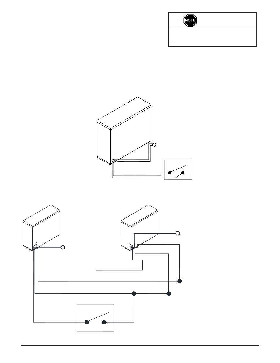
Multiple Unit - low Voltage Connections Direct Wired Controls
Figure 8
Notes: 1. Connecting the low voltage hot (blue) wire
from multiple heaters to a single control
switch may cause damage to the system. In
multiple heater applications, connect the
wires as shown for proper operation.
2. In this configuration, one outdoor sensor is
needed for each heater installed.
Installation 2.07
2100 Series
Single Unit - low Voltage Connections Direct Wired Controls
Figure 7
loW VoltAge Direct WireD PeAK control
If using the low voltage control option, the heater is direct wired to
the power company's peak control switch. Field connections from the
switch are made to the heater’s low voltage wiring harness through
the low voltage raceway. These wires are also accessible from inside
the electrical compartment. Class II (low voltage) wiring should never
enter a line voltage area of the heater, including its umbilical cord.
Some power companies also use anticipated (pre-peak) signals. If applicable to your installation, the control switch
providing the pre-peak signal can also be connected directly to the heater with low voltage wire. Refer to the Low
Voltage Connections Direct Wired Controls Diagram (Figure 7) for reference to peak and anticipated peak low
voltage connections.
If routing low voltage wire near line
voltage conductors, shielded wiring
must be used.
IMPORTANT
Control Switch
Peak
Outdoor Sensor
Gray
Gray
Blue/White
Blue
BACK OF
HEATER
BA
CK
OF
HE
ATE
R
Blue/White (Peak)
Blue (Hot)
Black (Common)
Blue (Not Used)
BA
CK
OF
HE
ATE
R
Blue/White
Outdoor Sensor
Black
#2
#1
Gray
Gray
Gray
Gray
Peak Control Switch
Outdoor Sensor
(See Note 2)
(See Note 1)
(See Note 2)
Low Voltage
Junction Box
Low
Voltage
Junction
Box