Important, Peak control – Steffes 2106 Owner & Installers Manual User Manual
Page 13
corD-connecteD (Plug-in) room heAting unitS
All cord-connected heaters are factory-
configured to be plugged into a 120V wall
outlet. The circuit outlet the heater is plugged
into should be designated solely to the
heater for circuit sizing purposes as well as
peak control and metering purposes in some
instances. To determine the correct circuit
size, refer to the Field Connection Wire and
Circuit Breaker Sizing Guide in this manual.
120V cord-connected room heating units
must only be used with receptacles that are
of the grounding type and suitable for the
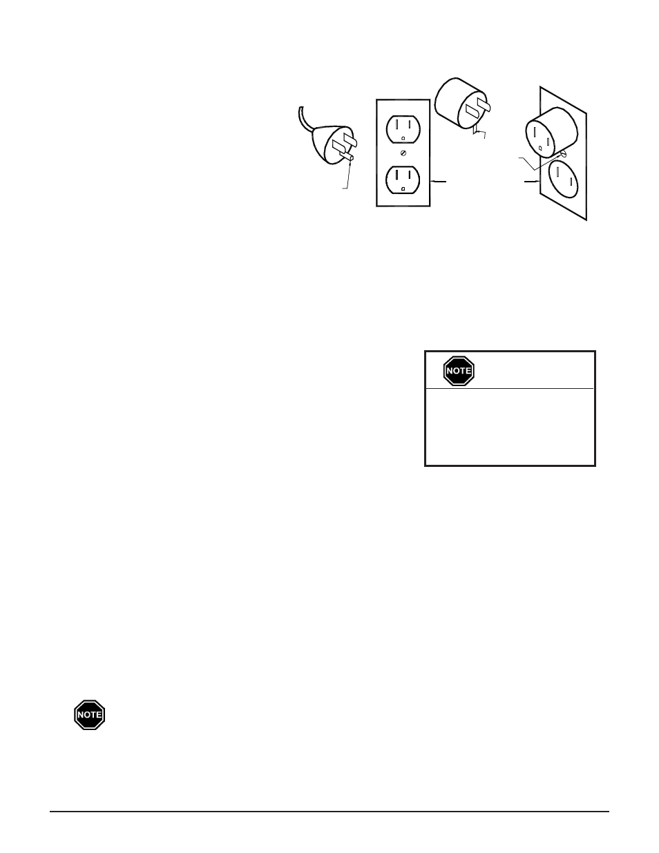
load of the heater. (See Figure 6 for cord and
receptacle requirements.)
The room heater's cord has a plug as shown in Figure 6A. An adapter, as shown in Figure 6B, is available for
connecting three-blade grounding type plugs to two-slot receptacles. The green grounding means extending from
the adaptor must be connected to a permanent ground, such as a properly grounded outlet box as shown in Figure
6C. This adaptor should not be used if a three-slot grounded receptacle is available.
PeAK COnTrOl
Steffes ETS heating equipment is generally controlled by the Power
Company via a peak control signal. This signal can be sent to the heater
using the Steffes Power Line Carrier system, low voltage wiring, a Steffes
Time Clock Module, or line voltage wiring. In applications utilizing
automatic charge control, outdoor temperature information is required and
can be received via an outdoor sensor or power line carrier control.
The 2100 series room heating unit is factory configured for use with power
line carrier control. Refer to the Configuration Menu (Page 2.10) for
information on configuring the heater for the application.
PoWer line cArrier (Plc) PeAK control
The optional Steffes Power Line Carrier (PLC) control system has the ability to communicate with the heater
through the existing electrical circuits in the structure. With the power line carrier option, hard wired low voltage
connections from the power company's peak signaling switch connect directly to the transmitting device. The
switch signals peak control times to the transmitter, the transmitter sends the signal to an unlimited number of 2100
series heaters, which receive this information and respond accordingly.
In addition to providing peak control signals, the transmitting device also provides outdoor temperature
information, room temperature set back, and anticipated peak utility control signals (if applicable).
As the PLC system is optional, it must be specified at the time of ordering. If utilizing a PLC system, refer to
the Owner's and Installer's manual accompanying the transmitting device for information on the installation and
operation of the power line carrier control system.
PlC Communication is very reliable in most applications but can be affected and hindered
by connection method used, electrical layout of the application, operation of other equipment
in the same electric system, dirty power, etc. Steffes Corporation does not guarantee effective
communication of the PlC system in all applications and is not responsible for any communication
issues outside normal operating malfunctions.
2100 Series
Installation 2.06
Never install any wiring
in the line voltage
compartment of the 2100
series heater unless it is
rated for line voltage.
IMPORTANT
120V receptable requirements
Figure 6
grounding Screw
grounding Means
grounding Pin
(Fig 6A)
3-Slot grounded
receptacle
grounded Outlet
Box (Fig 6C)
Adapter (Fig 6B)
2-Slot receptacle