Installation, Mounting the sf4 controller, Typical wiring – OEM Controls Superflex 4 User Manual
Page 6
file: SF4MAN.DOC
-
6 -
December 30, 1996
Installation
Mounting the SF4 Controller
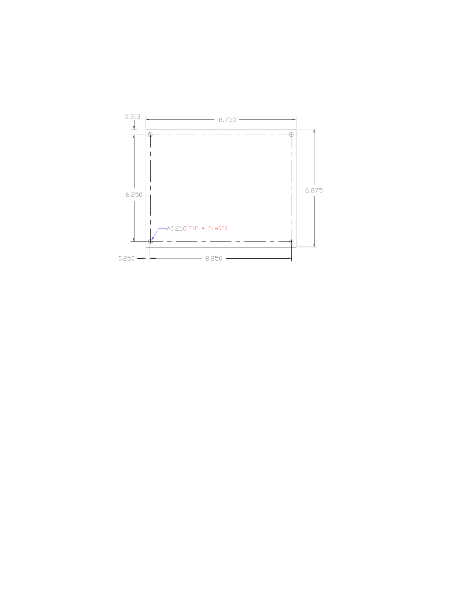
The Superflex Controller is an electronic circuit board assembly mounted on an aluminum plate. The
device can be mounted in standard enclosures or in another protected area. Mounting dimensions are
shown in figure 4. Allow at least 9 by 7 inches to mount the Superflex 4, and provide at least 3 inches of
clearance above it for the wire connectors and cable routing. (The Superflex 4 is approximately 1 inch in
height).
Since the Superflex 4 Control System is installed at the site of the machine’s final assembly there are many
installation variations. Follow these guidelines when installing or replacing the Controller -
"
Place the Superflex 4 in a metal enclosure, protected from rain and other fluids.
"
Be sure there are weep holes or one way drains at the bottom of the enclosure.
"
Use a minimum of 18 AWG wiring, especially on the power and output connections.
"
Install the wiring per SAE Specification J-1121.
"
Use 3 amp flyback diodes on all relay coils and non-proportional solenoid valves to prevent
EMI. Refer to the wiring drawing in appendix 5.
"
CAUTION - Provide external current paths when welding on the machine. Disconnect all of the
connectors from the Superflex 4 before welding to prevent damage to the system or to its wiring.
Typical Wiring
Inputs and outputs are controlled by the particular application’s software program that is built into the
Superflex 4. The function of various terminals are dependent on the application. The following sections
provide general guidelines for wiring the system.
Figure 5