Yamaha Foot Controller FC9 User Manual
Page 6
Attention! The text in this document has been recognized automatically. To view the original document, you can use the "Original mode".
LABELLING BY FUNCTION
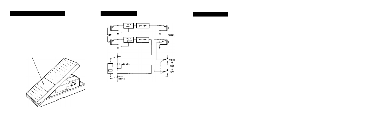
BLOCK DIAGRAM
SPECIFICATIONS
When using several FC9 foot controllers,
you may want to label each pedal by its
function.
Write the function of the pedal {e.g.
VOLUME,
MODULATION}
on
a
piece
of tape and stick it on this area.
Pedal angle
NORM position
Maximum input level
Input impedance
Resistance at MAX position
Resistance at MIN position
—70dB or greater
Output impedance
Input-output phase
CV position output characteristics
LED
Power requirements
Battery (006P)
AC adaptor (PA-1B)
Power consumption
Dimensions (W x H x D)
Weight
Supplied accessories
30
+8 dBm {9V battery use)
10 kohms
OdB
-20 dB (MIN VOL "10" setting)
—70dB or greater (MIN VOL "0" setting)
560 ohms
in-phase
B50k ohms (stereo phone plug inserted into Output 2 jack)
Battery indicator
9 V
12 V
5mA
116mm X 62mm x 246mm (4-1/2"
1.3 kg (2.9 lbs)
9V battery (006P) x 1
Owner’s manual
X 2-1/2" X 9-5/8")
A