Leica Geosystems PlusDraw User Manual
Page 14
11
Once a connection is established, follow the steps outlined below:
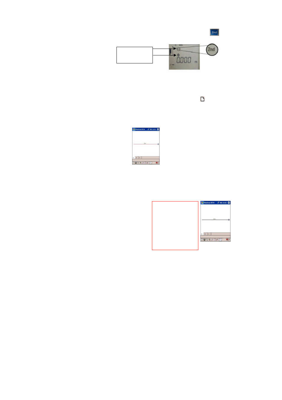
1) Make sure the 2
nd
Function Layer is activated on the DISTO- Press and ensure ‘2
nd
’
is displayed (
Image
19
).
2) If the devices are properly connected, and no pocket sketches have been created with
PlusDraw or Pocket Apex™, the Drawing View (TAB A as explained in the previous section) will
be displayed. You are ready to begin drawing an Area. However, if a sketch was previously
saved, every time the two devices are connected and PlusDraw is opened, the Document List will
display (
Image 11
). If this is the case, tap the new sketch icon on the toolbar. The Drawing
View will display.
3) Take a distance
measurement
using the DISTO*.
4) Input a
direction
using a directional key on the 2
nd
Function Layer. In PlusDraw, a red line
will be drawn in the direction that was indicated (
Image 20
).
.
*For more specific information on drawing using the DISTO product, please refer to the DISTO manual. The
DISTO manual contains helpful information on activating Bluetooth on the DISTO device for use with
PlusDraw, and for using the 2
n d
Function Layer. This layer will be used to send wall
measurements/directions directly to PlusDraw.
5) Press the
ENTER
key (2
n d
Function Layer). The line will be placed and colored black as
shown in
Image 21
.
Bluetooth connection
and 2nd Function
Layer are active.
Image 19
Image 20
Image 21
R
Before placing a line (when
it is red in color), the line length
can be quickly changed by
adding or subtracting
measurements taken with the
DISTO. For example, if you
have measured an 8 meter line
to the right and the line is still
red, you can measure 3 meters
to the left, and the resulting line
will be 5 meters in length.