Load limit switch, Table 5-1 – Dillon DynaSwitch User Manual
Page 17
17
The Dillon Cranegard Load Limit Switch is used to protect cranes and
hoists against overloading where it is impossible or inconvenient to use a
Dillon Dynaswitch. This unit can be applied to wire rope without cutting or
removing the dead end from its existing mount. It may also be used on
machinery such as elevators to provide a switch action at a given load.
The Cranegard is intended for applications with gradually applied tensions
and not dynamic or impact loads.
The Dillon Cranegard Load Limit Switch is designed to clamp directly onto
typical hoist or crane rope. It consists of two side plates. Two steel
sheaves which are equipped with precision bearings, a rope clamp and
center support which in turn is attached to a flexure. Arm(s) on the flexure
can actuate as many as four microswitches at preset load points. Adjust-
ment screws for the switches are located under a sealed cover.
The Dillon Cranegard Load Limit Switch flexure beam has a safety factor
of 2:l. Ultimate safety factor is a function of wire rope condition. In the
interest of safety, damaged or worn wire rope should be replaced.
The microswitch is type BZG1-2RN, weatherproof, Dillon P/N 17981-0048
(paragraph 1-7). As many as four switches can be installed on one
Cranegard unit.
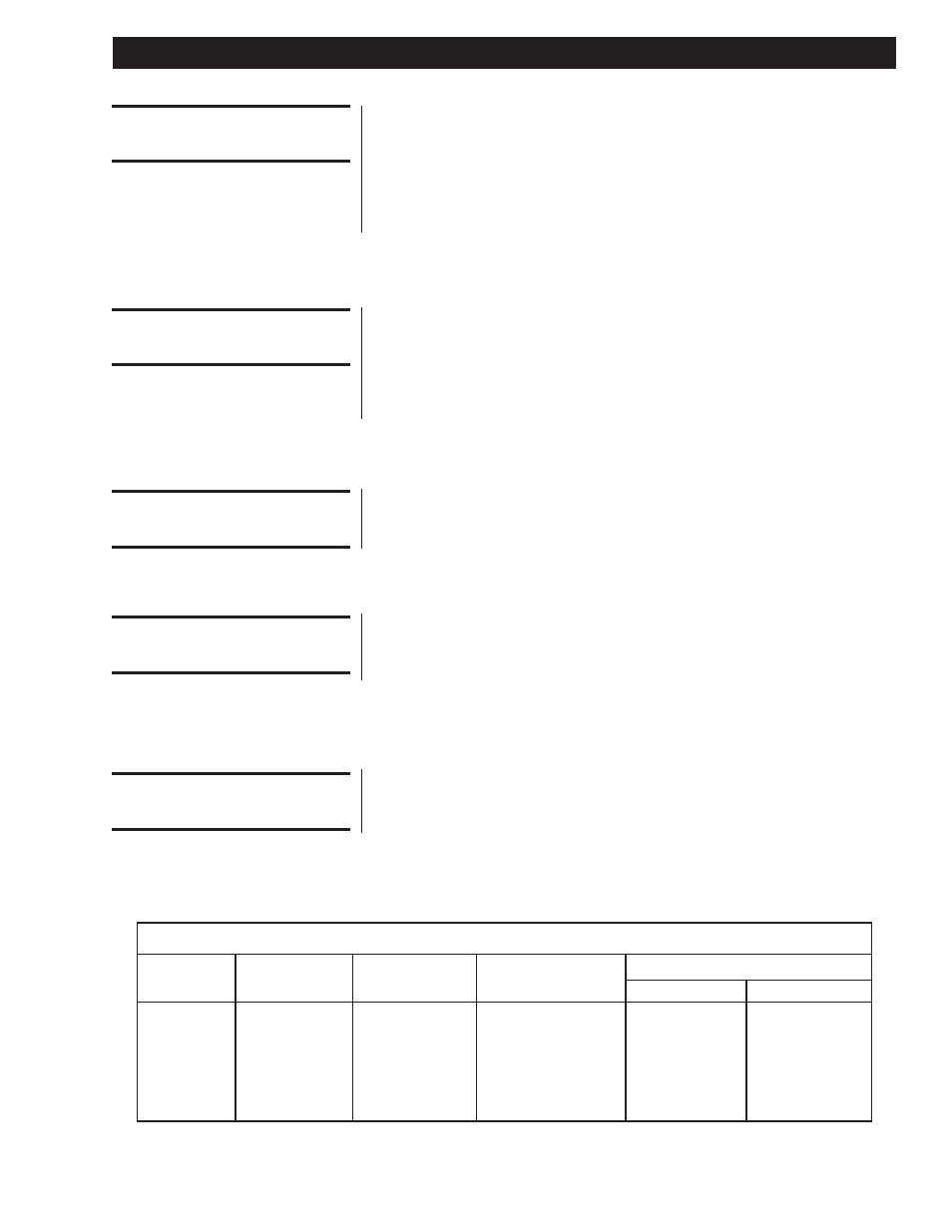
Table 5-1, below, indicates capacities and other specifications.
Section 5 Cranegard
®
Load Limit Switch
5-1
Introduction
5-2
General Description
5-3
Safety Factor
5-4
Micro-Switches
5-5
Key Specifications
Part
Capacity
Min. Set
Repeatability
Rope Diameter Inches
Number
Pounds
Point Lb
Pounds
CGS-1
2500
100
75
3/16
1/2
CGS-2
5000
200
150
3/8
7/8
CGS-3
10000
400
300
7/16
7/8
CGS-4
20000
800
400
5/8
1 1/4
Table 5-1
Minimum
Maximum