CANOGA PERKINS 9145E Network Interface Device User Manual
Page 31
Installation
9145E Ethernet Network Interface Device User’s Manual
Mounting Options
19
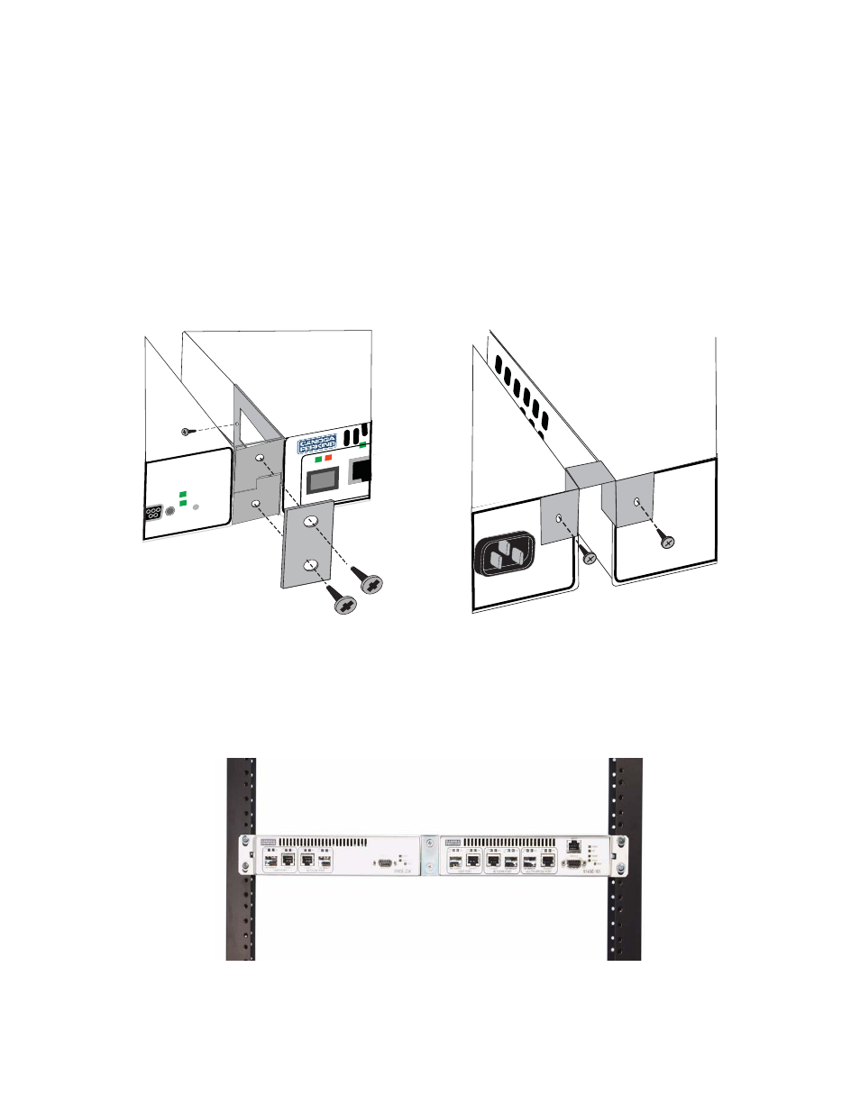
Mounting Two 9145Es, Side by Side, in a 19" or 23" Rack -
To rack mount two 9145Es,
perform the following steps:
1. Install the 19" Dual Unit or 23" Dual Unit Rack Mount Bracket Kit. The Rack Mount Kit
includes two rack mount brackets, two center brackets, a strap, a rear bracket, and the
screws required to attach the brackets to the 9145Es. The mounting brackets attach to
the two threaded holes on the outside of each 9145E, toward the front (see Figure 3-3).
The two center brackets attach to the two threaded holes on the inside of each 9145E,
and the strap mounts over the front of each center bracket (see Figure 3-5). The rear cen-
ter bracket is attached to the threaded holes at the top inside corner of the back of each
9145E (see Figure 3-6).
2. Place unit with brackets attached in place on the desired mounting rack.
3. Install two screws through each bracket into the threaded holes of the mounting rack (see
Figure 3-7). Torque the screws to the rack manufacturer’s specifications.
Figure 3-7. Mount Two 9145Es on Rack
Figure 3-5. Install Center Brackets and Strap
Figure 3-6. Install Rear Center Bracket
USER POR
T
LINK/
ACT
SPD
LINK/
ACT
RESET
POWER
STATUS
9145E-204