CANOGA PERKINS 9101 LAN Chassis User Manual
Page 17
17
9101 LAN Chassis
Canoga Perkins
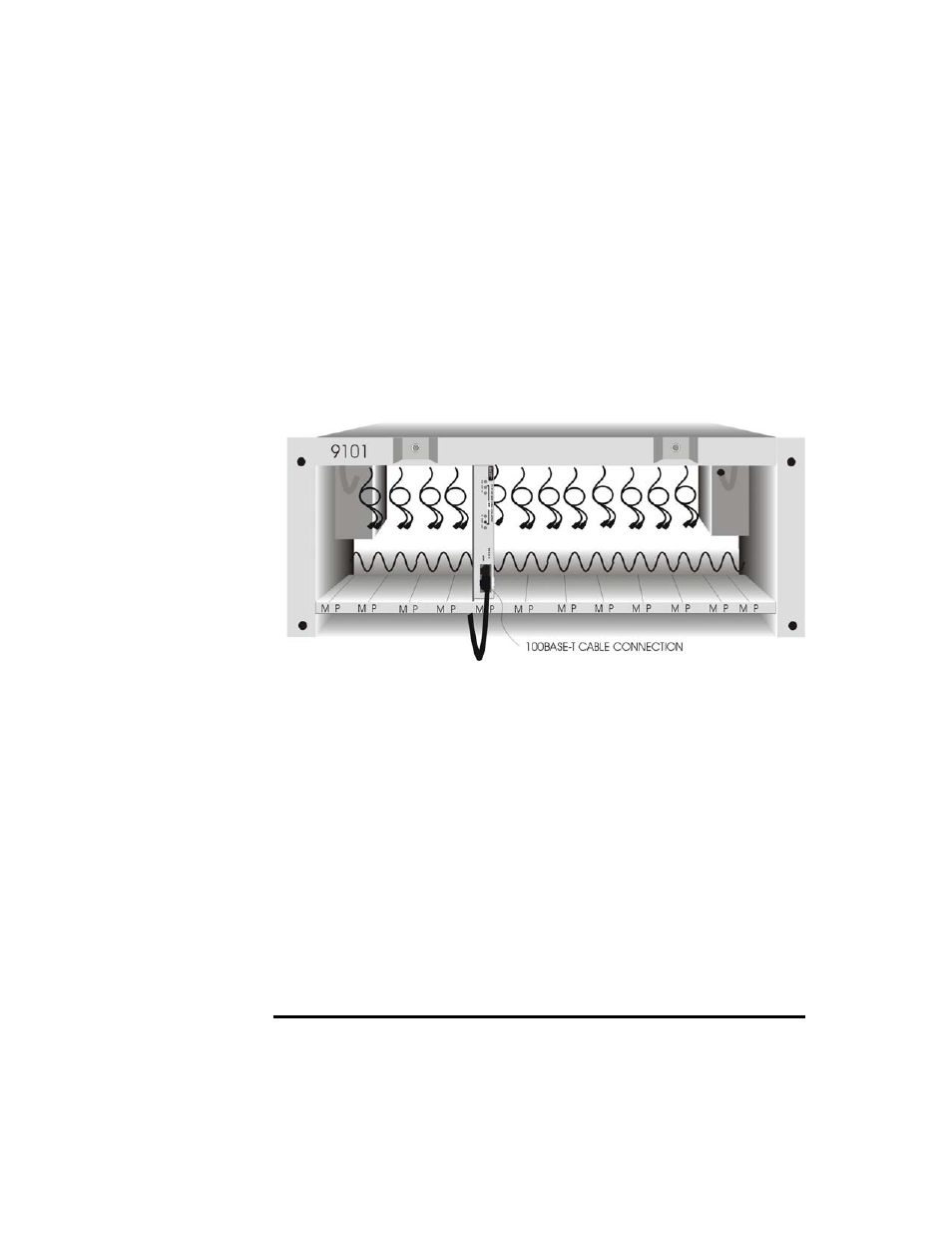
Step 4
Attach the 10BASE-T/100BASE-TX UTP cable by first bringing it between
the lower rack and chassis bottom, and extending it out the front. Then
insert the cable connector into the 8-pin modular jack on the front panel of
the 8829/9119 Media Converter (see Figure 3-6).
NOTE: Refer to the 8829 User Manual for proper setting of the "NORM/X"
switch, or the 9119 User Manual for proper selection of NORM or X
connector.
Figure 3-6
100BASE-TX Cable Attachment
on 9119 Media Converter
Step 5
It is recommended that once the circuit is confirmed operational, the
cables be tie wrapped in place to the cable guide. When doing this, ensure
that sufficient slack is left in the cables to slide the unit out of the LAN
chassis if it needs to be relocated or replaced.
Repeat Steps 1 through 5 for each media converter to be installed.
For operation of the 8829 Media Converter units, refer to the User Manual
(#6911550). For operation of the 9119 Media Converter units, refer to the 9119
100BASE-TX to Fiber Optic Converter User Manual (#6911560).
NOTE: Insertion of all card guides (9119 and 8829) does not pose a safety
hazzard. 9101 Chassis' can also be inserted into a rack without a
"1U" space between them without posing a safety hazzard.