CANOGA PERKINS 9101 LAN Chassis User Manual
Page 15
15
9101 LAN Chassis
Canoga Perkins
3.2 Media Converters (Models 8829, 9119)
Once the 9101-1, 2, 3 or 4, LAN Chassis is installed, the Media Converters may be
cabled and inserted into the chassis. Fiber Optic Transceivers and Media Convert-
ers can be co-located in this same LAN chassis, although only the Media Convert-
ers are connected to the power distribution board.
NOTE: Some configurations of the 9101 do not have the media converter DC
pigtails installed; therefore, it may be necessary to insert the pigtail
cables manually into the power distribution board prior to placement of
the units.
Step 1
Insert the appropriate pigtail connector into the Media converter:
•
8829 - (+24VDC), white-tipped plug, green/white wires
•
9119 - (+5VDC), black-tipped plug with green/black wires
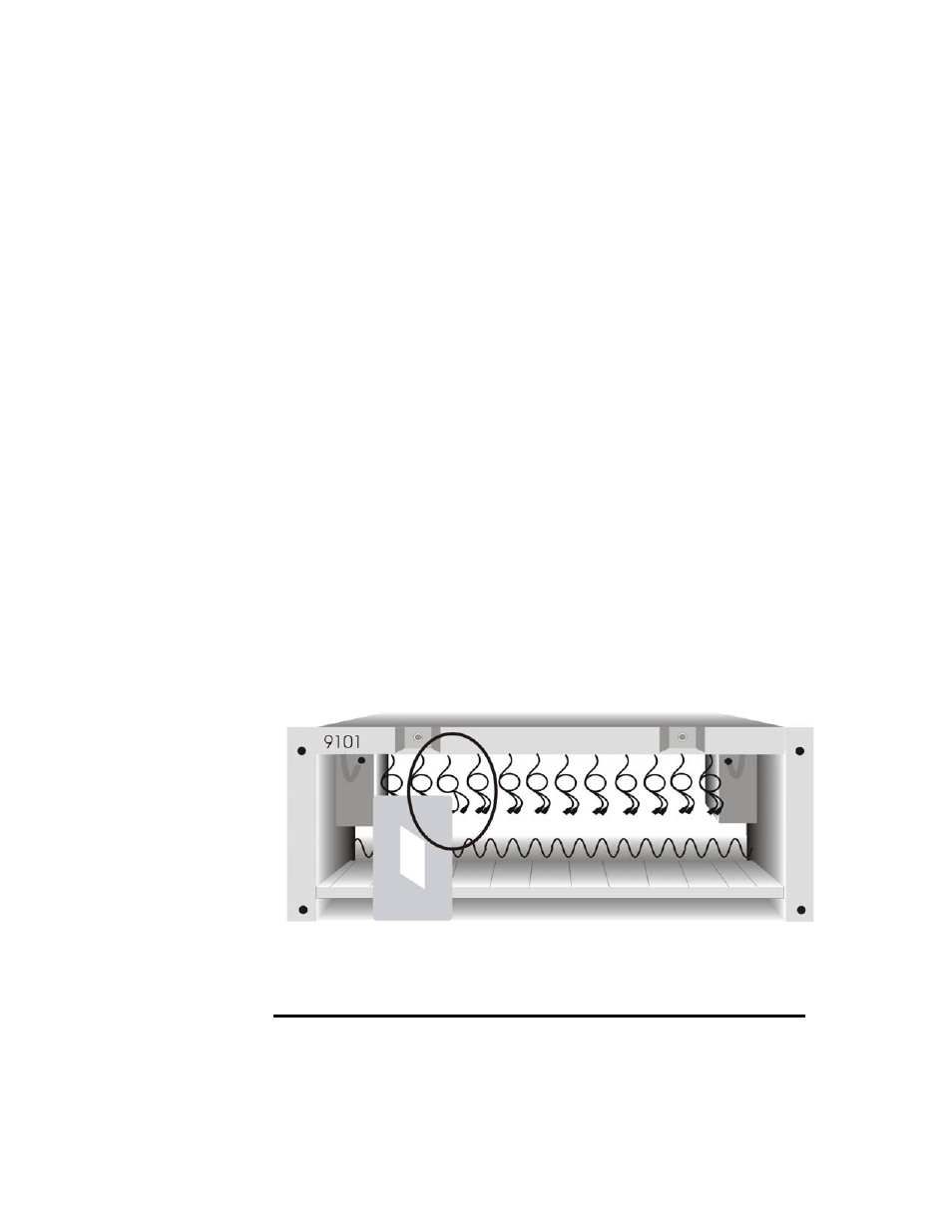
Reference Figure 3-3. Verify that the PWR LED indicator on the media converter
illuminates.
Warning:
The NEBs Level Three compliant pigtails are factory installed in the
9101, and a dual voltage pigtail is shipped with all media converters.
Warning:
It is recommended that the 9119 Media Converters be powered only
at the time of circuit activation.
Figure 3-3
Power Cable Connection
on Media Converter