1 interface module description – CANOGA PERKINS 9171 Metro Ethernet Routing Switch User Manual
Page 15
9171 Installation Guide
Proprietary & Confidential
Canoga Perkins Metro Ethernet Routing Switch
Page 15 of 26
Chapter 3 Fiber Interface Module and Cable
Connection Description
3.1 Interface Module Description
3.1.1 10/100/1000 Ports
Instruction:
10/100/1000 Ethernet interface can use RJ-45 connectors. Its maximum transmission distance is 100m. The
transmission of 100Base-TX and 1000 Base-T needs to use CAT 5 or enhanced CAT 5 twisted pair wires, or
CAT 6 non-unshielded twisted pair wires. While the transmission of 10 Base-T can use CAT 3 or CAT 4
twisted pair wires.
By default, 10/100/1000M auto-negotiation are enabled for RJ45 connectors for 9171 Series Routing Switch.
By this setting, when two switches are connected, the switches can automatically negotiate work environment
and parameters to be used in automatic configuration. If one switch does not support this feature, network
administrators or related personnel need to conduct configurations manually. See Configuration Manual for
specific manual configuration methods.
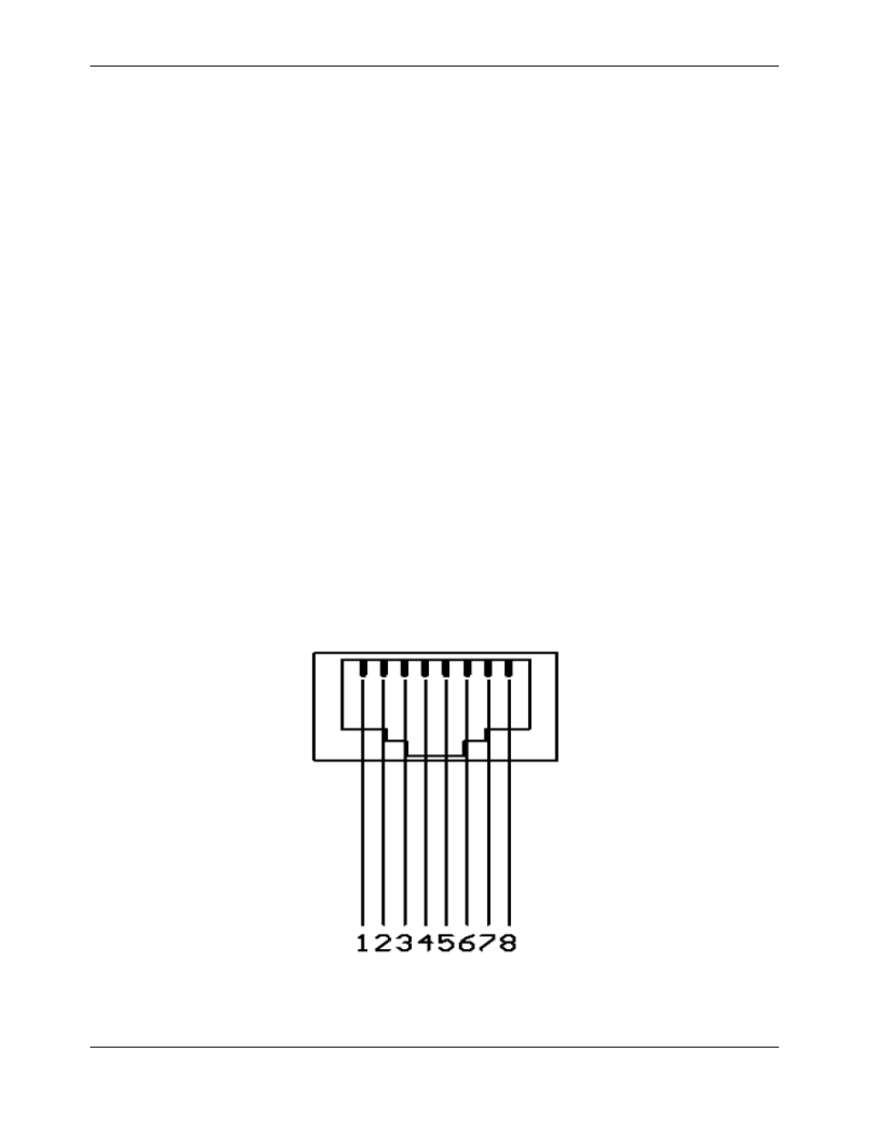
Definition of RJ45 Pins As Shown in Figure 3-1:
Fig. 3-1: Sketch Map of RJ-45 Connector Pins