Installing the 2-in-1 sensor – Beckett 7600 AquaSmart Boiler Control User Manual
Page 8
8
Installing the 2-in-1 Sensor
For proper operation,
there must be a secure
electrical bond between the green sensor
wire from the sensor and the boiler metal
vessel in direct contact with the boiler
water. Failure to secure an electrical bond
will result in the AquaSmart locking out and
displaying, “LOCKOUT - LOW WATER”.
Explosion,
Burn and Scald Hazards
Excessive water temperatures could cause
explosion, burns, scalding, pressure relief
flooding and fitting leaks.
y
The 2-in-1 Sensor shall only be installed by a
trained professional.
y
The sensor must be installed in the proper
location for correct low water cut-off (LWCO)
operation in accordance with the Boiler
Manufacturer’s instructions.
y
The 2-in-1 sensor body is installed directly into
the boiler wall tapped hole in place of an
immersion well.
y
Carefully follow the outlined procedures for
temperature sensor installation to ensure accurate
water temperature sensing and effective control
operation.
y
Make sure the plumbing for domestic hot water has
anti-scald valve protection.
y
Follow all applicable safety codes, rules and
guidelines for installing an immersion well.
Improper installation can result in the Boiler
overheating.
Do not use in steam
applications. For use in
hot water boilers or water heaters only.
Do not use outside of the intended use
and specifications.
Leak, Burn, and Scald
Hazards
Incompatible thread sealants could severely
damage the sensor threads.
y Only use Teflon
®
Tape or Rectorseal
®
No. 5
®
(soft-set).
y
DO NOT use any anaerobic fast-setting sealants
such as, but not limited to, Loctite
®
, Leak Lock
®
,
Permatex
®
, or Gasoila
®
.
y
Call RWB Technical Services at 1(800)645-2876
to confirm, if unsure.
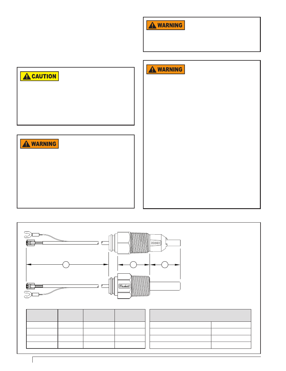
Note: There are two versions of the 2-in-1 sensor. The
76002N1SXX is an integrated single unit consisting of a
sensor and thermowell. The 76002N1RXX consists of two
components, a thermowell (7600TWXX) and a replaceable
sensor probe (7600PXX). The following instructions apply
to both versions unless otherwise specified.
Part No.
A
Lead Length
B
Insulation Depth
C
Insertion Depth
76002N1[
S/R
]01
8-1/4”
1-1/2”
1-5/8”
76002N1[
S/R
]02
6-1/4”
3-1/2”
1-5/8”
76002N1[
S/R
]05
5”
4-3/4”
1-5/8”
76002N1[
S/R
]06
8-1/4”
1-1/2”
7/8”
Figure 5 - Overall Dimensions & Specifications
Specifications
Storage Temperature Range
-40° to +250°F
Operating Temperature Range
32° to 250°F
Maximum Pressure
250 PSIG
Installation Torque Range (Screw-in)
185 - 200 in/lbs.
◄ 2-in-1 Integrated Sensor (S)
◄ 2-in-1 Field Replaceable (R)
A
C
B